• This forum is the machine-generated translation of www.cad3d.it/forum1 - the Italian design community. Several terms are not translated correctly.

Doubts line halfway

  • Thread starter Thread starter Alerm
  • Start date Start date

Alerm

Guest
Good morning to all
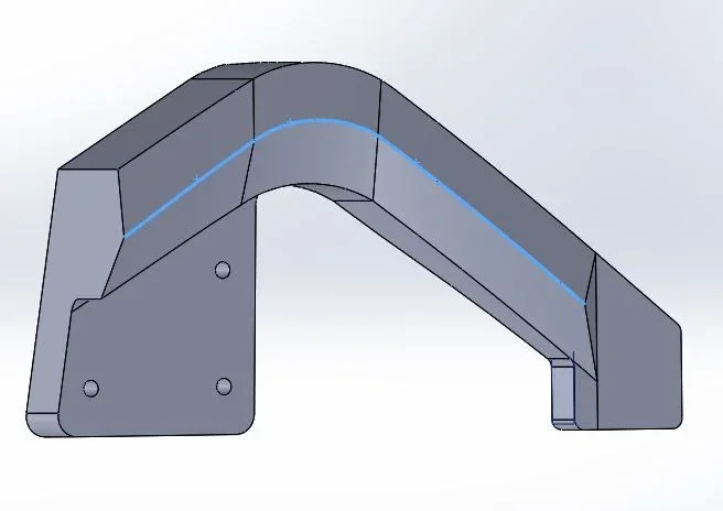
I wanted to know if you would recommend a simpler alternative to create a half-carry for the loft of this part.
I'm trying with 3d sketch but keeping the three size trend in shape doesn't seem easy!
Maybe there's an alternative I didn't think of:confused:

thanks to all
Cattura.webp
 
offset? symmetry?
Why do I sketch 3d?
If you'd attach the file you'd do first. is a house called, laughed and street yet you always have to beg 'you blessed files
 
from the mike that we are only at #8 post, well below average to have useful information
 
in the profile I wrote 2016 because it is that version I use mainly from work. as said this file is a draft because I am trying 2017.
but the problem doesn't seem to me to be the version of the program.
most users think will have no problem opening the file.
- - - updated - - - -
from the mike that we are only at #8 post, well below average to have useful information
note
 
in the profile I wrote 2016 because it is that version I use mainly from work. as said this file is a draft because I am trying 2017.
but the problem doesn't seem to me to be the version of the program.
most users think will have no problem opening the file.
No one has opened it for now. happy you all happy.
I don't think you would have a hernia or carpal tunnel syndrome if you had uploaded some screen with the three main views and an explanation in Italian current, clear, precise and syntactic as every technician should be able to do. the only one you posted doesn't need a bat because that visible sketch doesn't understand what it is for, as well as the only visible plan.

from the mike that we are only at #8 post, well below average to have useful information
Right?
What are you doing, are you fucking with us?
 
as said this file is a draft because I am trying 2017.
and of grace tell us in what precise post would you have said that is a file of 2017?
but the problem doesn't seem to me to be the version of the program.
most users think will have no problem opening the file.
the problem is that you do not give the correct information and those who try to help find almost always obstacles (file failure, unknown version...). based on what criterion do you think most will open the file? you are trying 2017 at the end of the year with the upcoming release of 2018; why should others be more up to date? many make the choice not to update every year and save if they manage to perform their work smoothly and if the new version does not bring some undoubted and significant advantage.
 
I've written "just" because it's been since I posted for the first time that I'm being noticed things that still go beyond any purely teaching advice.
in the sense that, to point out the fact of not having an updated profile, or to point out that it is necessary to avoid omitting to attach the files of the part, what right would we miss, when in this forum I will have you and no requested help 5 times, I seem more a dick rather than demands of what and how to do the to be done, explained by those who know more!
If I was wrong to upload the image, or need more info, just ask explicitly what it takes, without being too much to dwell on the fact that I was wrong.
I am not a habit of this forum, not that I would not like, but design for pure passion when I have time, and then on some things I still write a little ignorant about it, about the community and about who does it by profession.
As for my request for help. .I thought I was clear in putting my problem already from the first post, if for you however I spoke Arabic it would be enough to say, answer us all by posting photos of different views because we did not understand.
 
However, I try to explain myself better.
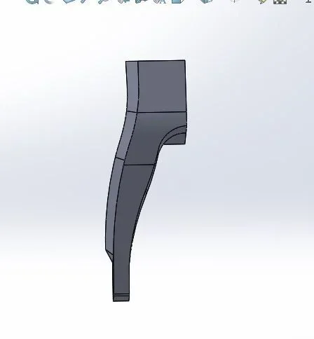
What you see in the highlighted photo is a loft extrusion, with the two edges, super and lower, which do as guide curves. 3.webpI would like to further improve the loft by adding a sketch with a half-mill like the one highlighted.5.webpthe part in its three dimensions, however, looks like this:1.webp2.webpso to create a half-carry as I would, the only way that comes to mind is by drawing a line with 3d sketch.
I want to know, is there another way to create it?
 
However, I try to explain myself better.
What you see in the highlighted photo is a loft extrusion, with the two edges, super and lower, which do as guide curves.
so to create a half-carry as I would, the only way that comes to mind is by drawing a line with 3d sketch.
I want to know, is there another way to create it?
If you just don't want to do the 3d sketch (for granted that you have to have your line of half-carry that drives the loft anyway in 3d) you can make on the vertical plane an extruded surface starting from the shape on that plane of your curve, then drawings on the plan offer it a curve that represents the course from that view and the projectors on the surface. the vurva thus obtained the use as a line of loft halfway. the method is rognose because you have to make the various end starting points coincide with the sections of the loft etc. at the end that curve is extremely simple as sketch 3d, regardless of whether it is composed of strings or whether it is a spline. with a bit of reference geometry (fixed constructions along the reference directions x, y, z) always inside the sketch 3d, controls all smoothly
 
Okay.
in fact to projected curve I had thought, although late. but in the end you are right, with sketch 3d, creating some references seems to be easier.

Thank you.
 

Forum statistics

Threads
44,997
Messages
339,767
Members
4
Latest member
ibt

Members online

No members online now.
Back
Top