• This forum is the machine-generated translation of www.cad3d.it/forum1 - the Italian design community. Several terms are not translated correctly.

extraction of a particular from a set

  • Thread starter Thread starter Luka Imperato
  • Start date Start date

Luka Imperato

Guest
Hello.
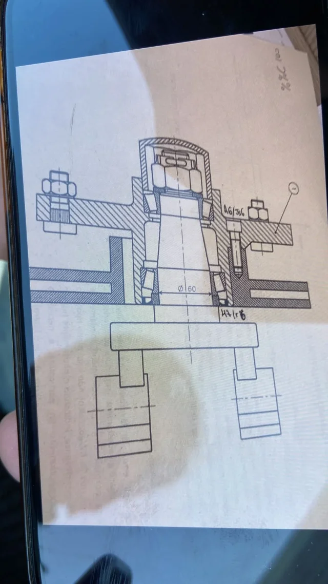
I am practicing to prepare the technical drawing exam, one of the exercises of the exam consists in the extraction of a particular from a total, with relative technological quotation and any dimensional/geometrical tolerances and indications on roughness (correcting possibly errors present in the representation).
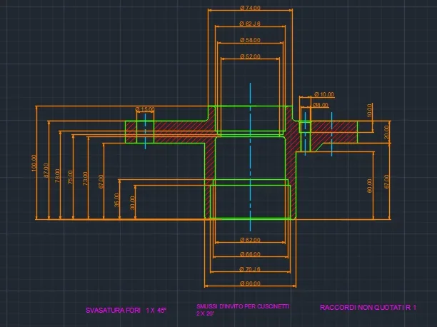
in the last call the total is that attached in photo, and I represented it in the following way.
My perplexity is as follows:
1 How is the particular seen from above? I initially thought it was a flange, but due to the fact that it is not asymmetrical hypotize cannot be.
2 Are additional dimensional tolerances necessary? the two that I have imposed are related to the fact that near those diameters will stay bearings.
3 are the two dimensional tolerances I have imposed? I hypothesized the couplings being base tree, so I established a lightly stuck coupling of good precision.

thanks for the attention, and I apologize in advance for any errors.
 

Attachments

  • Prova d'esame gennaio.webp
    Prova d'esame gennaio.webp
    176.9 KB · Views: 97
  • CAD 3d.webp
    CAD 3d.webp
    26.1 KB · Views: 88
if you do not have a second view you cannot know how the particular is done from above; when there was no 3d it was used to make even false sections, this could be the case (in fact to the left of the flange there is a lice that makes no sense) and therefore your particular is asymmetrical.
If you look down to the right there is a h7/r6 tolerance, it means that the flange is mounted to interference on the lower compass. There is also a tolerance, questionable in my opinion, on the tcei vine. could serve geometric tolerances.
J6 tolerances can go as well as not, depending on the function of the assembly.
the hole on the left does not understand how it is made: threaded but with rows quoted in the middle? The right hole is also wrong, where did you pull out all those diameters?
 
on the fact that without further views it is impossible to have a correct representation I agree. probably the left side of that flange (disegnata really badly)... can indicate a section maybe at 1200 to take the hole and therefore being an angular section should be stretched and for this reason takes a greater length.... but you have to be sick in the brain to give a trace so....vuol say I miss having looked before preparing it....the first random design we give it to students.
for dimensional tolerances we are. Surely it should be contextualized more and perhaps it is necessary to indicate on the casting of cast iron the geometric tolerances of crude jet.... but here we pass a little from the student to the professional.
 
Good evening, I'm sorry, but I forgot to say that the photo is made by a student, and I think the tolerances have been set up by him, so I don't know whether they are correct or not.
That said, the quotation on the hole on the left I have purposely taking as example the following present in the dispenses of our course, but I think I misinterpreted the eventual presence of threads .
As for the diameters, I did not understand whether it means the diameters referred to the right hole or those related to the central holes of the flange.
I tried to correct the hole on the right.
thanks for the attention
 

Attachments

  • CAD 3d terza foto.webp
    CAD 3d terza foto.webp
    22 KB · Views: 65
  • DA ALLEGARE CAD 3d.webp
    DA ALLEGARE CAD 3d.webp
    21.2 KB · Views: 38
to review also the style of quotas that is not in norm. the text must always be above the quota lines, horizontal for the horizontal and vertical quotas oriented to the left for the vertical ones.
quota 65 has no use because there is already 35 and then it would not be verifiable.
odds 87, 67, 20 (at which they are stunned because being asymmetrical you will have to draw the same shape you have made to the right) one of these must be in brackets because resulting from the other two; therefore decide what could be functional and adjust accordingly)
missing the length of the upper lower
missing a size of the down from 8mm to the right
 
That said, the quotation on the hole on the left I have purposely taking as example the following present in the dispenses of our course, but I think I misinterpreted the eventual presence of threads .
in the hole on the left you see a bolt, i.e. more rosette screw more nut, so being the screw blocked by the nut will have passing hole (what is locked in this specific design is one of the many mysteries of the exercise); what you took from your text is a screw hole.
also the right hole is passing because the thread is located on the compass; Try to think what you can block by screwing that screw...
As for the diameters, I did not understand if it means the diameters referred to the right hole
Exactly to those.

to extract a particular, when you are at first arms, you must take into account that the difference between the various details in the case of sections is represented with a deduction change; therefore it is useful to highlight the contour with a highlighter and consider useful only what there is content
 
read these discussions, which you will probably have already found in your previous search, but perhaps you have not read carefully:
 
ok I think I have understood, therefore regarding the hole to the left, will be passing as will be passing also the hole of the eventual other particular, and the two will be tightened thanks to the nut screwed to the thread of the bolt ( attach photo).
while the right hole (passer) serves to implement a connection with clamping screw?
further question, which represents this highlighted part?(second photo).

thanks for the links, I will study them.
 

Attachments

  • DA ALLEGARE 3 CAD 3D.webp
    DA ALLEGARE 3 CAD 3D.webp
    10.7 KB · Views: 31
  • DA ALLEGARE 2 CAD3d.webp
    DA ALLEGARE 2 CAD3d.webp
    10.6 KB · Views: 31
ok I think I have understood, therefore regarding the hole to the left, will be passing as will be passing also the hole of the eventual other particular, and the two will be tightened thanks to the nut screwed to the thread of the bolt ( attach photo).
That's right.
while the right hole (passer) serves to implement a connection with clamping screw?
Yes, look how the compass hole is made
further question, which represents this highlighted part?(second photo).
could be a particular type of screw since the head of the same is very low and does not have the lines that represent it as hexagonal.
 
perfect thank you so much, in the meantime I provided the correction of the design.
 

Attachments

  • Immagine 2022-02-28 215200.webp
    Immagine 2022-02-28 215200.webp
    20.8 KB · Views: 35
lack of quotas:
depth lamatura hole to the right
hole depth ø62 (27 is useless because those who do the processing cannot measure on the opposite side)
depth hole ø58
depth hole ø74

bearing housing holes (for shafts) must have an invitation bevel; the dimensions can vary, the length is proportional to the bearing and the angle is between 15 and 30 °. in your case it can go well a 2x20°
to want to be lazy the first part of the upper bearing hole will be wider to facilitate assembly, useless to force an element for a non-use, and to mount the cover that will surely not be tolerated to the cent.

the general snowing is sufficient 1x45°
general rayings are sufficient r1 (operated beam)
 
I corrected what you reported to me.
Good evening.
 

Attachments

  • DA ALLEGARE 5 CAD.webp
    DA ALLEGARE 5 CAD.webp
    20.1 KB · Views: 41
It is not a valid quotation. stop to think about how you would perform that detail, at its stages of processing, and then go back to look at the design.
 
I have to provide the operator with the quotas that allow him to understand what the diameters are, but also what the depths must be, but I have not understood how they are to be listed, is it correct to quote them as I did for the two holes below?
 
Last edited:
instead of asking questions step by step try to make a complete reasoning that then analyzes; without fear of wrong that you do not vote here.
look at some videos of how a milling and a lathe works and then do a hypothetical work cycle:
start taking the raw piece in this way
the first processing is this (what measures do I need to define it? )
the second is this (measures.... )
The third...

In this way you define how to place the necessary quotas and check that there are all
 
the particular you need to draw is a hub door circle of a car or a van and the screw on the left is one of the planting columns that serve to fix the wheel (see example).
This type of column has the flat and round head (sometimes it has a milling on the side) and the peculiarity consists in having a parallel zigrination on a diameter greater than that of the thread, which serves to create interference in the hole and avoid the rotation of the screw when screw is screwed or unscrew the nut. the planting must be carried out preferably with a press to avoid a possible misalignment of the screw that, subject to the stresses of the wheel, could suffer damage if not breakage.
then as for the hole on the left, it will be passing
Yes, the diameter must be slightly lower than the outer diameter of the zigrinata part in order to create interference, unfortunately I do not know how to give you exact values of tolerance to be adopted.
the size of the column could be those of the example I reported above and usually of these they mount 5 (furgons, machines of large displacement and off-road, 4 in the smaller cars).
based on this number (5) I also assumed the use of 8 tcei m8 screws.
 
Last edited:
Okay, all clear, the indication of the sectional plan made me clear the ideas.
I have tried to correct the quotation, adding quotas that allow to understand where the holes are made, and explicitly adding the various depths of the central holes.

thanks for the availability.
 

Attachments

  • Immagine 2022-03-01 111454.webp
    Immagine 2022-03-01 111454.webp
    20.8 KB · Views: 62
I also tried to sketch out a possible shape of the flange based on your section and the considerations I made in the previous post.
Actually, in the left view of the section I should also see the next popspec in sight.
n.b. It's an illustration design to make it more understandable, so you'll need to see it with the standard technical drawing rules.
 

Attachments

the quotas of the holes oer the screws never give from a diametral edge; listed by the central axis.
the thickness of the flange you listed it to sinstr ain one way and right in another, why?
the thickness 2 of the hole del252 is a resultant quota and therefore should not be put; instead the hole ø62 how does it get?
one of the fundamental things of the technical design is that an opertator should never make calculations of the size to be obtained.

It would be useful, for you of course, if you added the reasoning of the work that you hypothesized as I advised you to do.
 

Forum statistics

Threads
44,997
Messages
339,767
Members
4
Latest member
ibt

Members online

No members online now.
ciao
Back
Top