• This forum is the machine-generated translation of www.cad3d.it/forum1 - the Italian design community. Several terms are not translated correctly.

ilogic (configurations or adjustable shares)

  • Thread starter Thread starter falcorsv
  • Start date Start date

falcorsv

Guest
Hello everyone, I looked in the forum and also externally but I feel like I didn't find answer to my question.
I clarify my problem, I have a particular for example a cylinder ø100, this cylinder has a
length of es.1000mm of which I made the detailed table. Now I have to place this cylinder
in different assemblies with different lengths e.g.900, 1100, 1200, etc., so that when I make a
change to that l=1000mm the changes I get also on those of other sizes, but of which I do not want to make a table
for other lengths. since I don't want to use iparts and iassembly I thought I would use ilogic so
preset the various lengths, and I managed to do what I wanted but unfortunately I noticed that however
creates a family of parts (which I did not want to use and for which I found the system to make up) but
However in environment together when changing the variable length also changes the variable length
of the particular standard that should instead remain fixed (I hope to have been clear).

practically I would like to achieve something that in sw is called configuration and in itself adjustable part.
Thank you for your attention and I hope someone can help me.
 
Last edited by a moderator:
assuming that I don't know how you set your ilogic, and I don't know what the functions used in the design are, but if what changes is only the length and other functions are the same and with the same values, I think you should use iparts.
would be a very simple method and if you had to change something you would have it on all the lengths planned.
If you still want to continue using ilogic try to upload the file I might try to look at. . .
 
hi, I did a test and in the hope of understanding, here is the result:
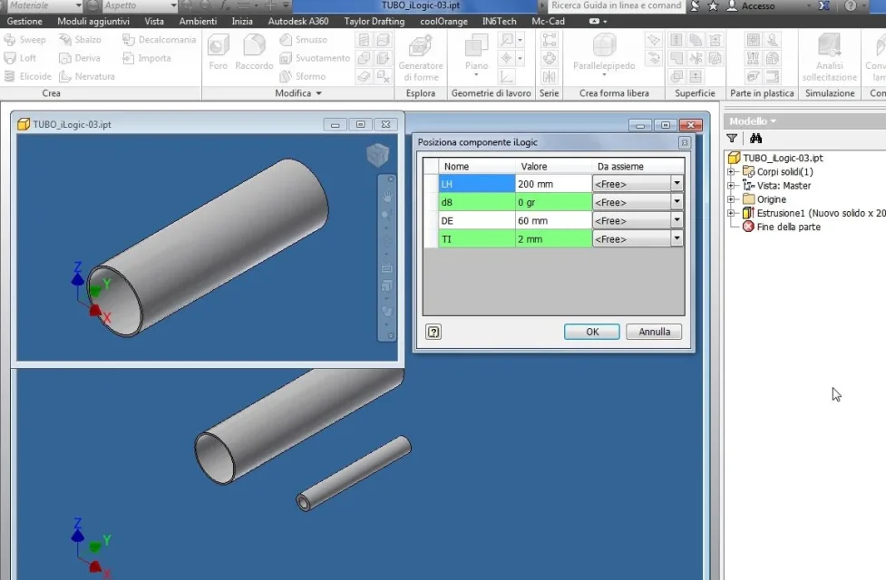
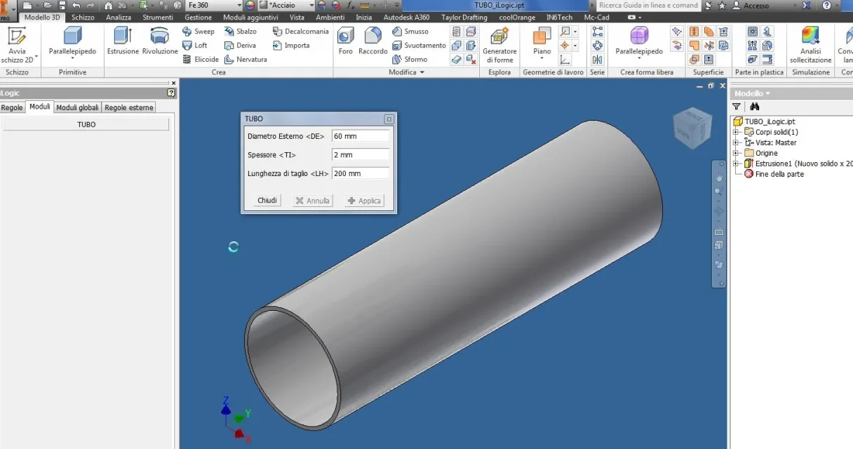
I created a part file (tubo_ilogic.ipt) with input forms
tubo_ilogic.webpthis file can then be handled individually and scaled through graphic input

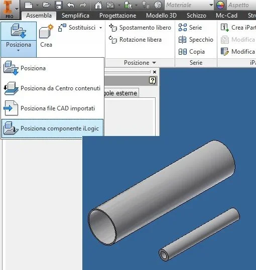
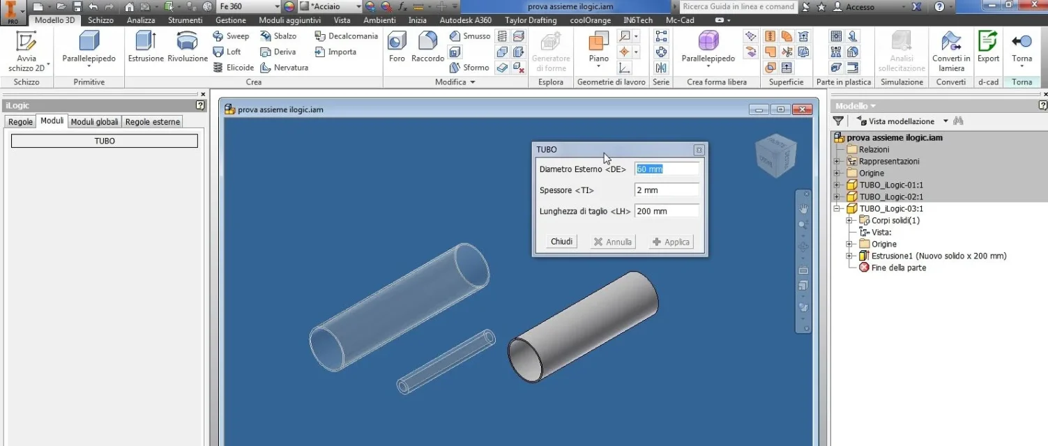
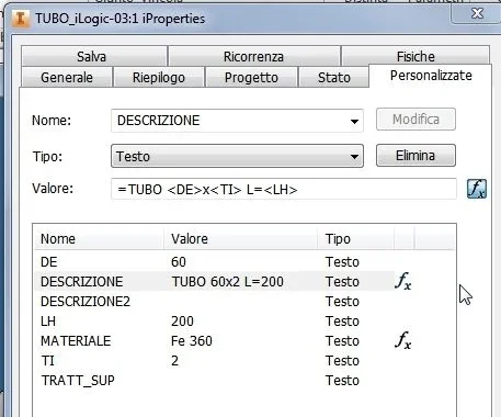
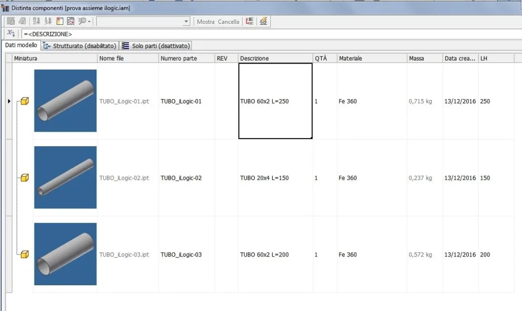
or, if loaded into a set, through the command "places ilogic components,"ilogic_assieme.webpthe interface "simplified" with the request of the size, at the same time, comes to duplicate the tube_ilogic.ipt creating a new file totally independent from the "source" (because, it is not a derivative part).inserisci nuovo tubo.webpthis file may however be modified at any time by changing the partmodifica parte.webpSince dimensional properties are exported and managed in the "custom iproperties", the description and cutting length, are automatically updated to vary the sizecustom iProperties.webpdistinta.webpallego files used for photos in the examples... in the hope of being useful to all


you can watch videos and download free other ilogic parts that I made on the grabcad website
https://grabcad.com/library/plate-2-holes-1https://grabcad.com/library/shaft-with-ilogic-1Good job
 

Attachments

thank you 1000 and excuse the late answer, I will put into practice your advice trying to deepen and if it is the case I will disturb again.
 
No trouble! is a pleasure, the important thing is to be useful

Good job
 
this file can then be handled individually and scaled through graphic input

Sorry, in the ilogic browser I find no rule, but I saw that you created a module....and in the parameters there are 3 sizes....how did you manage so all? I'm sorry, but I can't understand. Can you explain it to me?
 
this file can then be handled individually and scaled through graphic input

Sorry, in the ilogic browser I find no rule, but I saw that you created a module....and in the parameters there are 3 sizes....how did you manage so all? I'm sorry, but I can't understand. Can you explain it to me?
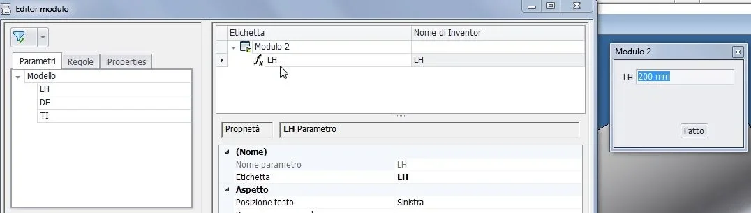
Exactly. then if you open the file individually (photo 1) or change it from within the axieme (through the edit command or double mouse click) (photo 4) in the ilogic browser, in the module tab, you have the interface of the selected file ready for the editing input.
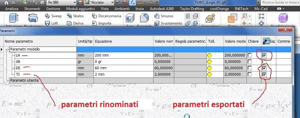
without creating rules, you can create modules that simply recall the values of fx parameters that you have renamed and exported
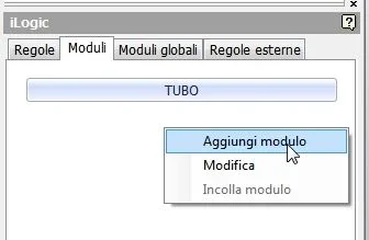
(1)Fx parametri.webp2) creates the module (input interface)_foto__111.webp3) select the parameters to load_foto__112.webpif you are looking for youtube, there are many videos on the topic

Hi.
 
Hello, matteo,
following your example I created a rivnut (ilogic part).
I wonder if there is a possibility that when inserting the file into a set have the name of the new suitable part like "rivnut m5 mild steel" or "rivnut m8 stainless steel"
Thank you.
 

Attachments

Forum statistics

Threads
44,997
Messages
339,767
Members
4
Latest member
ibt

Members online

No members online now.
Back
Top