• This forum is the machine-generated translation of www.cad3d.it/forum1 - the Italian design community. Several terms are not translated correctly.

in don't understand logic

  • Thread starter Thread starter TECNOMODEL
  • Start date Start date

TECNOMODEL

Guest
I would need a clarification about the sketches in inventor.

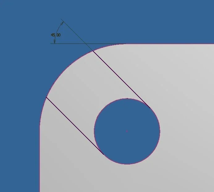
I have a detail with a hole that I want to open like asola to the outside.
I project the edge of the hole and the outer one, I build 2 lines with appropriate constraints and coincide with the geometries projected.

At this point, however, the projected geometries cannot divide them into a part of construction and the remaining to close my profile.

I can not even use the sketch to make a cut extrusion because the profile is not closed.

Do I have to create 2 arches and bind them to projected geometry?

seems strange as a method, leads to a lot of lines many of which overlap:confused:

I attach an image if I have not been clearCattura.webp
 
Unfortunately you are right, inventor struggles to identify certain regions and sometimes it is very annoying. in your case however the solution is simple, I would do so:Foro Tagliato.webp
 
inventor struggles to identify certain regions and sometimes is very annoying
Of course, if you're wrong, you go hunting in a dead end.
in this case the proposed solution requires (1) the projection of a reference, (2) the use of a simple geometry ( rectangle not aligned to the base terna ), (3) the application of a bond on the center of the hole, (4) the angular quota and the tangence between the fitting of the piece and side of the rectangle (this bond is redundant ).
It seems to me that there is the least essential, I doubt that any other cad does so with fewer steps.
simplicity helps in all cases and adds resistance to changes, but inventor is objectively "dispectful" in this field: specifically I tried to do the thing that I wouldn't do (and that technomodel tried without success) and obviously it works perfectly today, I think it is because the piece and the sketch are "clean". However I use only inventor and therefore I do not know whether it is a common difficulty to all solid modelers or a specific limit of inv...
 

Attachments

  • Foro Tagliato 2.webp
    Foro Tagliato 2.webp
    9 KB · Views: 7
Of course, if you're wrong, you go hunting in a dead end.
in this case the proposed solution requires (1) the projection of a reference, (2) the use of a simple geometry ( rectangle not aligned to the base terna ), (3) the application of a bond on the center of the hole, (4) the angular quota and the tangence between the fitting of the piece and side of the rectangle (this bond is redundant ).
It seems to me that there is the least essential, I doubt that any other cad does so with fewer steps.
Well, other cads do it more easily.

on solidworks I just have to do 2 straights with the vertices hooked to the edges that I am not obliged to project because it recognizes them as entity, put a tangency bond on the edge of the hole and just.

with 2 straights I get what with inventor I get with 2 projections of edges, a rectangle and various constraints, as you also said redundant.

It seems to me that at the least indispensable it is a little abundant.

then of course I have to work with inventor, so I ask to understand it better and use it effectively.
inventor can do the same.
what I indicated is the minimum path for a novice, although I consider it as explicit as possible and the easiest to manage by anyone and not only from the top-driver of the office, which makes half the steps of the niubbio.
 
inventor can do the same.
what I indicated is the minimum path for a novice, although I consider it as explicit as possible and the easiest to manage by anyone and not only from the top-driver of the office, which makes half the steps of the niubbio.
even with inventor can you do it?
Would you explain how?
That's why I'm asking on the forum, the help of experienced users can make me grow sharply and quickly.
 
Would you explain how?
This is done exactly as you described.
Two straights that know they have to be parallel, two vertices attached to the external lines of the reducer ( lines that are automatically recognized), the other two parallel and tangent vertices to the circumference of the hole, which is automatically projected, the final extrusion.
all this without using the automatic projection of the edges to the creation of the sketch, which seems very comfortable but, in fact, it is heavy and source of problems in the face of variations of future geometry.
I still prefer my system.
View attachment prova lavorazione.pdf
 
This is done exactly as you described.
Two straights that know they have to be parallel, two vertices attached to the external lines of the reducer ( lines that are automatically recognized), the other two parallel and tangent vertices to the circumference of the hole, which is automatically projected, the final extrusion.
all this without using the automatic projection of the edges to the creation of the sketch, which seems very comfortable but, in fact, it is heavy and source of problems in the face of variations of future geometry.
I still prefer my system.
View attachment 40101
I do not use automatic projection because, as you rightly say, it only generates confusion.
It is not clear to me however how you make the lines automatically recognized and how the hole circumference does to be projected automatically.
 
I do not use automatic projection because, as you rightly say, it only generates confusion.
It is not clear to me however how you make the lines automatically recognized and how the hole circumference does to be projected automatically.
click on matching constraint icon, touch the end of the line, touch the hole.
also this is longer to describe than to do.
 

Forum statistics

Threads
44,997
Messages
339,767
Members
4
Latest member
ibt

Members online

No members online now.
Back
Top