beccamort
Guest
I've got to laser the tubes that intersect. the cut must be perpendicular to the circumference, exactly as the laser does. How do you do that?
I hope I've been clear.
I hope I've been clear.
Do the tube like this:Yes, with inventor.
I mean something else. doing as you say the "cut surface" is not perpendicular to the circumference in every point, which is what I need. while cutting the tube the laser is always radial compared to the tube.
the suggested medote from tarkus can work.Do the tube like this:
-Revolution of surface (suppression)
-cut surface with the inclination or profile you want
- thick thickening desired.
so you get perpendicular
Allow me: perpendicular and normal are synonymsthe suggested medote from tarkus can work.
you can also use the edge of the surface as a trajectory for a sweep (swwp of a normal segment at any point at the sweep curve).
ps: because you continue to complicate your existence by saying "..perpendicular to the circle, to the surface etc..." is said "normal" to the surface and it is impossible every mis-understanding. :biggrin:
but if you want to make a tubular taken, for example, from the contained center?Do the tube like this:
-Revolution of surface (suppression)
-cut surface with the inclination or profile you want
- thick thickening desired.
so you get perpendicular
so it works only in certain cases, in the subsquadri you will find interference. there are two methodologies at geometric level, then you have to apply them to inventor.Do the tube like this:
-Revolution of surface (suppression)
-cut surface with the inclination or profile you want
- thick thickening desired.
so you get perpendicular
Of course there are some interference in the substations.so it works only in certain cases, in the subsquadri you will find interference. there are two methodologies at geometric level, then you have to apply them to inventor.
...............
Bye.
both with proes and with solidworks when converting into sheet metal the interferences are eliminated and in the development the cut is formed by two sweeps in which the junction points are clearly visible. These joint points coincide exactly with the point where the support passes from external thickness to internal thickness.Of course there are some interference in the substations.
There are also in reality cutting with laser-tubes.
and these interferences obviously increase when the thickness increases.
I do not know any parametric cad that has the function of calculating the thickness interferences in the interconnection of profiles.
These functions are found in other typical programs of sheet and lattonery development.
logitrace to say one... but no parameterization, nothing; only the naked and raw development!
Sure. Of course.Allow me: perpendicular and normal are synonyms
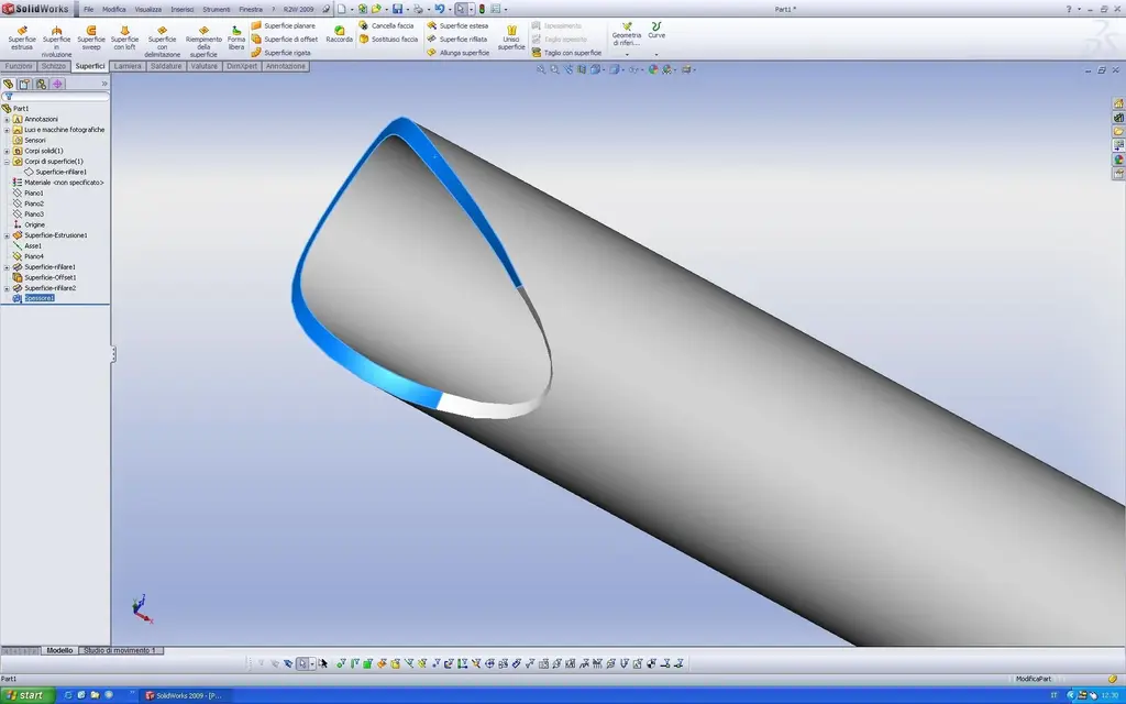
Can you post an image where you see the two tubes at the junction point?place an image. it can be noted that the cutting surfaces are 2 edges that delimit them are the exact point where the support on the other tube passes from inside to outside.
In this case I modeled a ø127 tube that is 45° on a tube of the same diameter.
a man of little faith... have a few sections. 45° trunks are modeled separately: one with the sheet function and one with the surface method.Can you post an image where you see the two tubes at the junction point?
for charity, but what little faith, I would only want to see the construction, but if I don't ask too much and you can post the solidworks files. . .a man of little faith... have a few sections. 45° trunks are modeled separately: one with the sheet function and one with the surface method.
Of course I was joking. :biggrin:for charity, but what little faith, I would only want to see the construction, but if I don't ask too much and you can post the solidworks files. . .
anyway honor and glory to solidworks
natives and steps....Of course I was joking. :biggrin:
What do you want to see? do you place the natives or iges/step?