You are using an out of date browser. It may not display this or other websites correctly.
You should upgrade or use an alternative browser.
You should upgrade or use an alternative browser.
Onda
Guest
and what questions should we ask? to make a shell mesh with hypermesh simply push a button. .
acatra83
Guest
vabò. .
as usual the modesty you have.. .
the model is already compiled with plies of composite material (tsai-wu theory) and is ready for a modal analysis.
wave.. .
I don't have to help you...
♪
as usual the modesty you have.. .
the model is already compiled with plies of composite material (tsai-wu theory) and is ready for a modal analysis.
wave.. .
I don't have to help you...
♪
Onda
Guest
It's not immodestia, but to help you tell us the choices you made.
have you meshato on the average line? on the outer edge? on the inside one? How did you solve the internal solids? and the problems at the hub.
doing a mesh with hypermesh is easy, but you have to make assumptions for the work done is valid. I believe that to help Uncle Charming you have to explain to him these assumptions. ie how to switch from a solid model of solidworks to a mesh model ready to be analyzed.
I would like to make mesh on the outer shell so as not to change it whenever you decide to change the lamination plan and then the thicknesses.
Let us see the mesh made without explaining these assumptions is not of help.
then what property did you give him? What materials? Uncle Charming hasn't posted them yet.
You stepped forward, didn't you?
ziocantante
Guest
composite material is a prepreg formed by an epoxy resin matrix and a carbon fabric.
I attach an image with features.
The foam is called rohacell and high-twire, thus assuming structural function (to lighten the structure and have the rim entirely in carbon and reduce its thickness as much as possible).
I attach another image with the characteristics of the foam.
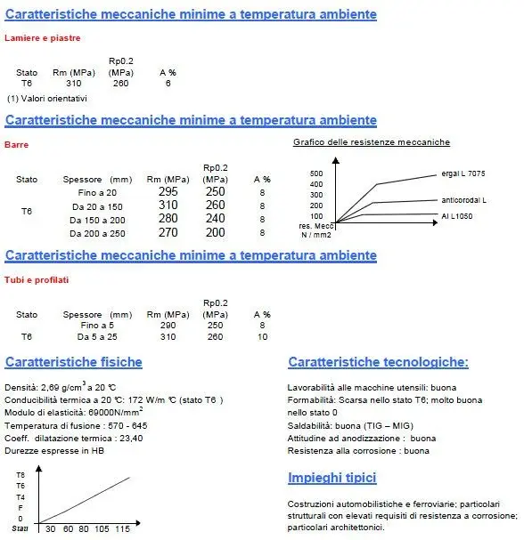
a aluminium alloy will be used for the hub area.
I attach image with features.
These are the data that provided me with the company that will produce the circle.
in the light of this I think that the model that acatra posted was what I had in mind but nn can realize with hm.
I have to start from mesh (as you do and what kind) and learn to define the properties of materials, constraints and loads.
Would someone take me by step?
by wave: I understand what I should do, but I can't do it on the program. what was the problem of importing in hm the geometry produced directly by solidworks? Why is it better to work on a third of the circle? and above all, how do I replicate everything I did on that third to get the full piece?
by acatra: did you say that the model you did is already compiled and ready for modal analysis (to understand, is ready for study of behavior under static and dynamic load? ? ).
Could you guide me in the steps to get the model you made?
I don't want to make anyone work, but I'd like to learn how to use the program properly, at least as far as my case is concerned.
I attach an image with features.
The foam is called rohacell and high-twire, thus assuming structural function (to lighten the structure and have the rim entirely in carbon and reduce its thickness as much as possible).
I attach another image with the characteristics of the foam.
a aluminium alloy will be used for the hub area.
I attach image with features.
These are the data that provided me with the company that will produce the circle.
in the light of this I think that the model that acatra posted was what I had in mind but nn can realize with hm.
I have to start from mesh (as you do and what kind) and learn to define the properties of materials, constraints and loads.
Would someone take me by step?
by wave: I understand what I should do, but I can't do it on the program. what was the problem of importing in hm the geometry produced directly by solidworks? Why is it better to work on a third of the circle? and above all, how do I replicate everything I did on that third to get the full piece?
by acatra: did you say that the model you did is already compiled and ready for modal analysis (to understand, is ready for study of behavior under static and dynamic load? ? ).
Could you guide me in the steps to get the model you made?
I don't want to make anyone work, but I'd like to learn how to use the program properly, at least as far as my case is concerned.
Attachments


Onda
Guest
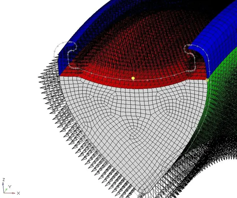
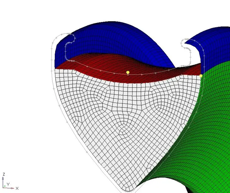
because in solidworks you make an external surface and an interior of the skin thickness and if shell models you have to hold only one of them or the intermediary. Usually, if you produce an external mold, you mesha on the external surface so you can change the laminate (often) without having to change the mesh.by wave: I understand what I should do, but I can't do it on the program. what was the problem of importing in hm the geometry produced directly by solidworks? Why is it better to work on a third of the circle? and above all, how do I replicate everything I did on that third to get the full piece?
with composites the intermediate surface is used little.
It is not better to work on a third of circle. is normal (but depends on habits), work on the minimum of surfaces and then copy mesh.
simply make a copy of the mesh on another comp. then roll the 120° comp if this creates problems you can work on the whole circle.
or work on the third circle, fix the surfaces, cover them on another comp and wheels of 120, do the same and the wheels of 240. then do the equivalence of the surfaces and do the mesh of everything.
all this because the model is not meshable immediately, but it is necessary to slightly change the surfaces to the hub and the tooth that keeps the cover.
I think the model's critical point is the hub interface.
acatra83
Guest
in fact,
The problem is at the hub.
You better work on primitive solids.
I'll explain.
eliminates the connection rays between the rays and the hub.
mesha primitives by changing new geometries through intersections between solids.
I think it's very complex for you though.
question:
but do you want to meshare everything to the tetra of the second order (parabolic) and then cover with skins? ?
do qst proposal to prof.
for what concerns the materials, the prepreg is fine, to simulate as mat8 of nastran.
while for rohacell you have to simulate it with the mat9
Hi.
Onda
Guest
to use the covered elements:
nastran shells are typically cquad4 or cquadrs (and related ctria3 transition elements and ctriar.
use triangular elements of the second order I do not see a great solution. for what I know is used only in the case of solids covered where the structural part is supported by solids. Let's not forget that the mesh shell is the one that carries the load while solid mesh represents only the foam and brings essentially the cut between the skins. therefore I would say that it is not admissible meshare to tria of the second order regarding the mesh to shell.
regarding materials:
for the foam you need the elastic cutting and tangential module (and its polka dot coefficient), then the modelling with linear elastic isotropic material (mat1).
with regard to the composite (carbon) you miss the elastic cutting module in the top and off the top. If you do not put skins at 45° this module is essential.
about geometry: I proposed an iges file with a hub simplification. It's worth considering if it's valid.
This is why you first need to decide how to simplify and then make mesh, which is the easiest thing when you decided the assumptions and changed the geometry accordingly.