• This forum is the machine-generated translation of www.cad3d.it/forum1 - the Italian design community. Several terms are not translated correctly.

modeling advice

  • Thread starter Thread starter volaff
  • Start date Start date
Good evening,
I have this file step that asked me, somehow, to ralize from head trying to make it sufficiently parametric for any changes.
Honestly they are definitely in the high sea being not accustomed to reasoning in terms of sforms, ect ect.

Could someone tell me a strategy to start?
Perhaps you should also use the superifices to realize at the end a solid but I would not say corbellers.

All I can do is thank you.
Good evening!

fly
 

Attachments

hi volaff, if you have to parameterize a file like this you have to have a certain idea of what may be the changes, if it is to move the poppets you will make certain choices, if it is instead to move from a shape to 'saponetta' to a square form, then the speech changes a little.
Second, you talk about sforms, the piece, as I saw it, presents a closure made a little like that, to the eye. I used the command that I have in nx to extract isocline to 0° regarding the direction of molding and the bottom radius is not in sform, if the piece is aesthetic and unpolished in mirror needs a minimum of sform otherwise you can mark in extraction.
 
It doesn't seem so complicated to me.
remodel the part above that existing by making trivial convert entities on the linear parts and using three-point curves on the curved parts.
Do the extrusions, cuts and everything. during these steps hide/show the imported body to verify the reliability. when the part is ok delete the relationships from the edge and start to quota with the parametric logic that you have set yourself.Immagine.webp
 
ua.
I don't see any surgery in your tree.
I'll be brutally rude, but couldn't you attach the file to help me understand the sequence of operations you've done through the feature tree?

thank you in any case always for the disability.
Say hi.

fly
 
How can you see no operation? But that you've sold out?
and all that after imported1?
Extrusion
Agreement
empty extrusion
....
 
I'll be brutally rude, but couldn't you attach the file to help me understand the sequence of operations you've done through the feature tree?
equally brutally, no!
to make that model I used basic functions, nothing that anyone has a minimum of familiarity with software can not and should know how to use. then I turned on the real view to give it a touch of pussy
in private I have already told you my opinion about your work situation and the idea not only does not change, but following your few (although legitimate) demands has become unsatisfied. shut down.
I give you answers, advice and anything else not because you are, but because I have something to say about the issue and the good use of the software. but from here to do files that serve to save your ass at work because those who do not put under conditions their technicians to learn the job, time must pass.
 
equally brutally, no!
to make that model I used basic functions, nothing that anyone has a minimum of familiarity with software can not and should know how to use. then I turned on the real view to give it a touch of pussy
in private I have already told you my opinion about your work situation and the idea not only does not change, but following your few (although legitimate) demands has become unsatisfied. shut down.
I give you answers, advice and anything else not because you are, but because I have something to say about the issue and the good use of the software. but from here to do files that serve to save your ass at work because those who do not put under conditions their technicians to learn the job, time must pass.
the truth in the end was good the right step for..
was to understand how to handle future requests.
What do you mean? thanks the same for the advice, always precious!
Good evening

ps: you charge any step like that as complexity and I try to shape it we see how I do the cable, I don't know what to say :)
 
If I take my step, what do you understand more than you have uploaded?
you have the function tree, try to make the model and then you correct it together.
advice:
parts from the base leaving the small rays, those on the corners of the quadrilateral, as function to itself.
extrude and empty the thickness of the walls
 
If I take my step, what do you understand more than you have uploaded?
you have the function tree, try to make the model and then you correct it together.
advice:
parts from the base leaving the small rays, those on the corners of the quadrilateral, as function to itself.
extrude and empty the thickness of the walls
All right, thank you.
account to do so on weekends, home and services allowing.

a small curiosity: how did you treat the sform on the inner and outer wall?
 
I didn't do anything wrong.
Maybe I looked at it superficially, I ran off the lower bombings. . .
leaving those for the last as addition or subtraction material to study the rest remains equal, do only an extra extrusion.
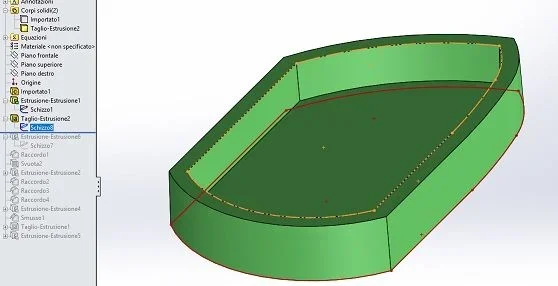
in practice do the first extrusion of the shape with a sform of 1.5° then dig of 4,5 with a sform of 2°Immagine.webp
 
I took it easy to do it again. Incognita is the precision of equality because there are measures, especially some rays, which are not obtainable with the simple measuring instrument. So I went a little to the eye.
considering the sforms I would say that it was designed to get it from casting or mold so I do not think that the great precision of the shape is necessary.
Anyway, I'll coach you.
a pdf with the overlap of the two bodies; in shady brown the original one, in green pea what made me
the step file so you can verify the overlap and measure decently (the radius of the silhouette are those obtained from the convert entity and I left them with those stupid decimals)
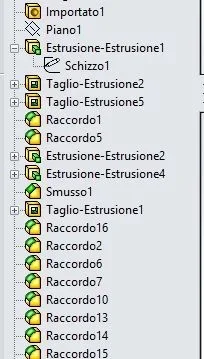
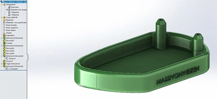
the feature tree of the new model of which I give a small explanation below
- the plan serves because the origin is placed in the upper part while the shape from which I left is located in the lower part
- first extrusion of the full shape with 15° shape
- cut to empty by making a 2mm offset and a 2nd sform
- cut to make the lower bombing that develops in one direction
- external and internal rays (other than those of the pins) of the vertical edges
- extrusion of the two pins from the inner bottom with 2nd shape
- extrusion of the flanks of the pins with 2nd deformed
- bevels and pinholes
- series of rays of the various advanced edgesImmagine.webpView attachment pezzo.pdfView attachment pezzo. massivon weizen.zip
 
Good morning.
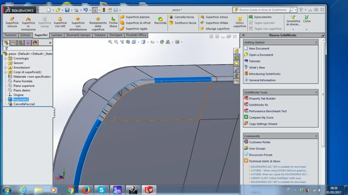
to extrude the "base" profile (because there is the radius) I had thought to delete the faces along the edge and then "extend" the surfaces so as to realize a kind of "virtual shape" to define the base profile.

What do you say? Could be a good input?

Thank you all.
Good day!
 

Attachments

  • Immagine.webp
    Immagine.webp
    95.3 KB · Views: 2
Good morning.
to extrude the "base" profile (because there is the radius) I had thought to delete the faces along the edge and then "extend" the surfaces so as to realize a kind of "virtual shape" to define the base profile.

What do you say? Could be a good input?

Thank you all.
Good day!
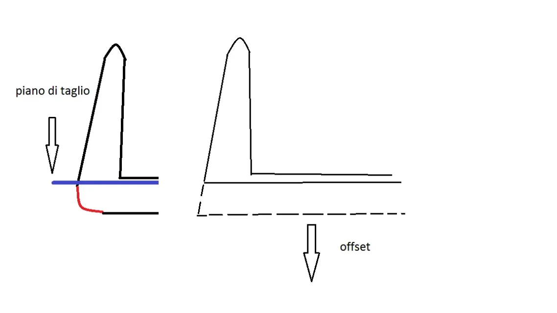
without doing all this mess you don't know where you take a horizontal plane just above the radius, cut the 'saponetta' with this plan and then give a offset to the face so obtained.
you place an image made with a stratospheric cad (paint because I do not have nx underhand :-) )
I hope I explained.
Hi.
 

Attachments

  • offset.webp
    offset.webp
    9.5 KB · Views: 2
without doing all this mess you don't know where you take a horizontal plane just above the radius, cut the 'saponetta' with this plan and then give a offset to the face so obtained.
you place an image made with a stratospheric cad (paint because I do not have nx underhand :-) )
I hope I explained.
Hi.
We thank you so much for the answer in the meantime but... doing so that I get? I'll explain.

If I have understood once I have done so I get a face that I don't understand what you need.
I think I've misinterpreted.
 
it is a offset of the profile of a few cents of millimeter. Losing for these things makes no senseImmagine.webp
 
you put on the front floor
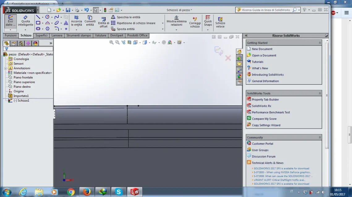
open a sketch
convert edge entities.
Leaving those virtual sharpe craps of, exaggerating, tenths of a millimeter.
to the maximum then finished all and quoted the sketch you will rule with the quotas the silhouette
 
thanks for the answers.
I have understood that you mean (look figure then change the profile with quotas); to do something more "correct" already upstream I wanted to realize the cagata de virtual shape but, as I set it up, I should pass for the ect ect superifici.

There is no more just approach than another perhaps.
as there was the sform I thought starting from how I wanted to set up was "didactically" more correct.
That's all.
 

Attachments

  • Immagine.webp
    Immagine.webp
    77 KB · Views: 2
as there was the sform I thought starting from how I wanted to set up was "didactically" more correct.
definitely yes, but academically.
in the current context it makes little sense considering the measurements and type of object that, as it is structured, should be obtained from fusion and already well that the millimetres will be respected.
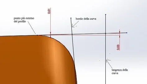
but always at an academic level you must define where the projection plan is located; as you see from my image there is a difference between doing it at the end of the radius or tangent at the curve that creates the lower bombing. in the last case a true virtual shape is just not possible to do it but you have to create an intersecting point the edge and the plan.
returning to modeling: by converting curved edge entities you will get splines that are little manageable (and result of generation from an imported model); you should use the bow with three-point modes, select the edge ends and adjust by hand the ray (or put a sketch point about half board and use it to bind us the third point of the arc)
 

Forum statistics

Threads
44,997
Messages
339,767
Members
4
Latest member
ibt

Members online

No members online now.
Back
Top