• This forum is the machine-generated translation of www.cad3d.it/forum1 - the Italian design community. Several terms are not translated correctly.

modeling advice

  • Thread starter Thread starter volaff
  • Start date Start date
without doing all this mess you don't know where you take a horizontal plane just above the radius, cut the 'saponetta' with this plan and then give a offset to the face so obtained.
you place an image made with a stratospheric cad (paint because I do not have nx underhand :-) )
I hope I explained.
Hi.
I don't understand your strategy.
 
the piece is distorted both internally and externally so with a plan taken as described by you "I do not take" all the part of the adi surface above the radius.
 

Attachments

  • 002.webp
    002.webp
    96.8 KB · Views: 2
  • 001.webp
    001.webp
    83 KB · Views: 2
Now that I could look better at the file, I saw that the part below is pretty bombed.
put two parasolids, one cut with a 0.5 mm top from the inner surface, the other with the face under 'offsetata' of 2 mm.
I took off the rays so that you, possibly can take the edges above to make an estusion.
I've measured it's 1.5°.
the surface below consists of a series of patches very messed up, it is not easy to extract and extend them.

I hope I helped you. Hi.
 

Attachments

Thank you very much.
I would like to understand the strategy so that it can be implemented in sw, since for now this is the software I'm using.
would you be so kind to tell me?
I'm sorry if I ask too much.
Thank you!
 
Good morning.
I tried to realize the particular in question.

I tried to extract the profile of the object by importing the surfaces of the connected part (red in figure), I did an extrusion in one direction and in another making a cut with a plan
tangent to the upper edge following this procedure-.

1) convert profile net of connection radius;
2) extrusion of the profile by tot mm from one la3to and the other
3) cut extruded profile with a passing plan for the bribe at the edge
4) emptying (how do I determine the thickness for such function)
5) internal reform
6) external sform
7) How do I make the bombed part on the other side?
8) Piolini
9) holes
10) fittings

I stopped at point 4, failing to determine the thickness of the part to be empty.
good Sunday to all and thanks always for the collaboration.

ps: I could prenede the thickness in the files that you have trained me kindly but I would like to understand materially how to make
a greeting

fly
 

Attachments

  • 1.webp
    1.webp
    54.6 KB · Views: 1
  • pezzo.rar
    pezzo.rar
    727 KB · Views: 5
I had done in post with function tree and their explanation. What more do you want?
 
Good morning.
I tried to realize the particular in question.

I tried to extract the profile of the object by importing the surfaces of the connected part (red in figure), I did an extrusion in one direction and in another making a cut with a plan
tangent to the upper edge following this procedure-.

1) convert profile net of connection radius;
2) extrusion of the profile by tot mm from one la3to and the other
3) cut extruded profile with a passing plan for the bribe at the edge
4) emptying (how do I determine the thickness for such function)
5) internal reform
6) external sform
7) How do I make the bombed part on the other side?
8) Piolini
9) holes
10) fittings

I stopped at point 4, failing to determine the thickness of the part to be empty.
good Sunday to all and thanks always for the collaboration.

ps: I could prenede the thickness in the files that you have trained me kindly but I would like to understand materially how to make
a greeting

fly
you place three files:
a step with the curves of the inner and outer profiles of the tray and of the poppette a dwg with the same curves if you do not load the step and a step with a similar surface (equal not because it takes too much time) to that below.

I don't know what to do anymore. the sform is 1.5°
Hi.
 

Attachments

I have to try to understand alone because the sform is 1.5°; just measure with the tool "measure" the sformed face with a straight segment parallel to that face.
 
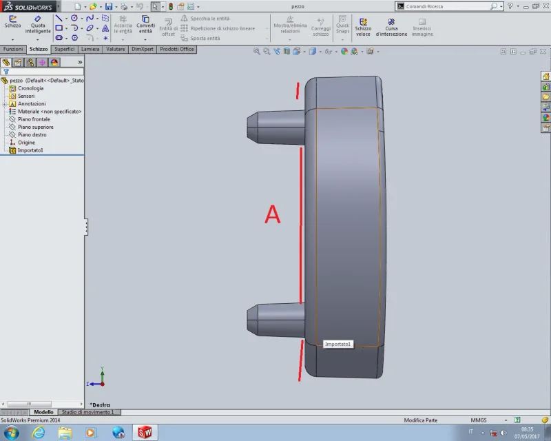
just for clarity I attach the original piece with qupote of the sforms and a couple of odds of encumbrance
green tangency linesImmagine.webp
 
Good morning.
I tried to realize the particular in question.

I tried to extract the profile of the object by importing the surfaces of the connected part (red in figure), I did an extrusion in one direction and in another making a cut with a plan
tangent to the upper edge following this procedure-.

1) convert profile net of connection radius;
2) extrusion of the profile by tot mm from one la3to and the other
3) cut extruded profile with a passing plan for the bribe at the edge
4) emptying (how do I determine the thickness for such function)
5) internal reform
6) external sform
7) How do I make the bombed part on the other side?
8) Piolini
9) holes
10) fittings

I stopped at point 4, failing to determine the thickness of the part to be empty.
good Sunday to all and thanks always for the collaboration.

ps: I could prenede the thickness in the files that you have trained me kindly but I would like to understand materially how to make
a greeting

fly
I have tried to do so by following my ladder, even because in your tree I have not seen sforms so it is more complicated for me; to determine the thickness of the part I measured 1.86 mm between face and face but I do not know if it is truthful as part thickness.
Am I wrong with this methodology? and how do I cut from the other open to the base of the usual if it is unformed?
Can I somehow circumvent the obstacle?
 

Attachments

updated with the reforms.
even if I have a 0.03 mm offset

How can I do to make the lower bombing now that, on the side, has inclined edge trace? ?

Thank you very much
 

Attachments

I can't see the file now. tell you in speed that efforts apply them to extrusion and cutting functions
 
the phrase before is "I tell you" we give thanks to the insensitive thumbs and the automatic concealer of the #@&&&? We do that you took me for exhaustion and later I attach the file, which certainly has gaps due more than anything else to the ignorance of the final goal.
 
I did a little update.
would at least be interesting to compare the different strategies adopted, I also used a move face beyond the sforms.
 

Attachments

thank you so much for the file tonight or tomorrow I give him an eye since my laptop went ko and I have to fix it.
I have just noticed that in my profile if I don't answer the tangence (if I use the convert entity) in making the connection I have tangent propagation problems.
 
Hello, everyone.
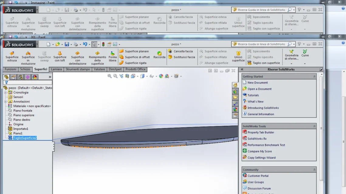
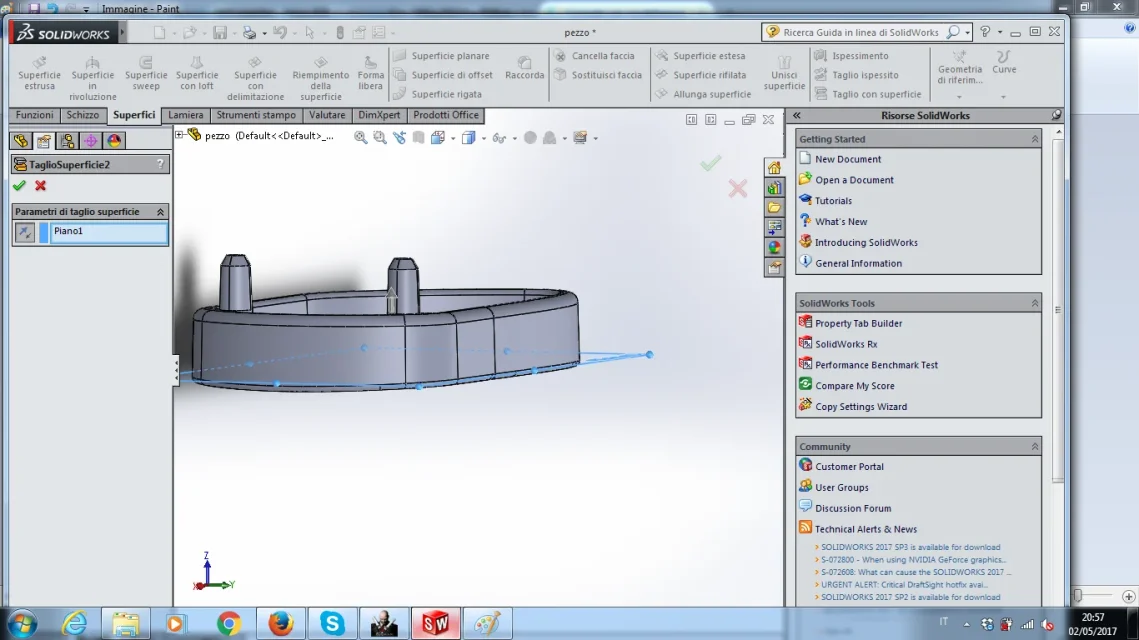
I came to this point and I don't know if I did well.
I had to add a face shift compared to the sform to "align" the faces.
how do I determine the size of the thickness, being the molded piece both internally and externally?

I chose a little particular way to make this piece.
Thank you all.
 

Attachments

Forum statistics

Threads
44,997
Messages
339,767
Members
4
Latest member
ibt

Members online

No members online now.
Back
Top