• This forum is the machine-generated translation of www.cad3d.it/forum1 - the Italian design community. Several terms are not translated correctly.

modello in ansys workbench 14.5

  • Thread starter Thread starter dacorsa
  • Start date Start date

dacorsa

Guest
Bye to all,

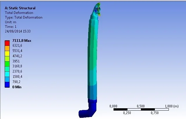
I am here to ask you something of ansys, I did this model with solidworks and I imported it into ansys as a step file (which difference is in importing as solidworks files?), I defined the part that will be studied as ink and applied a linear deformation on the edges you see in photo, that is the entry of this flexible stainless steel. Now the problem is that I don't know how to tell ansys to also apply a rotation of the edges, a rotation of 8°, how do you do it? I found in "displacement remote" the possibility to insert a corner but then the model in the simulation deforms in an incredible and unrealistic way. How can I do that?

Thank you.
 

Attachments

  • Picture0003.webp
    Picture0003.webp
    23.2 KB · Views: 24
I now realized that on the environment bar and clicking on supports there is the "fixed rotation" option but it is grey... why?

I tried to select a border, a point, a surface but it always remains grey....I don't know how to do it.

I hope some of you know, thank you soon
 
never used that bond.
Maybe it's not for static analysis?
Did you look at the help?

But what do you have to do? evaluate the voltage state by turning the 8° system? Could you explain yourself better?
 
you find force and moment applied assigning deformation and rotation, good you guessed!
I didn't look at the help cmq
You know how to do that?
 
what you imported is a solid and not a surface.
solution: remote displacement

greetings
 
Bye to all,

I tried to make simulation for the deformation of this steel "arm" consisting of 2 tubes, an interior with 2 mm thickness and an external of 3 mm. assigning the deformation of 20 cm to the extreme high and assigning the disaster to the lower one the result is that in photo...an unexpected and unrealistic deformation. Can you advise me something? How should I set ansys to solve this type of structures? Any notice to make mesh? I also attach three messages received during the solve.
 

Attachments

  • Picture0001.webp
    Picture0001.webp
    7.7 KB · Views: 50
  • Picture0002.webp
    Picture0002.webp
    11 KB · Views: 49
  • Picture0003.webp
    Picture0003.webp
    14 KB · Views: 49
  • Picture0004.webp
    Picture0004.webp
    13.4 KB · Views: 49
Clearly the boundary conditions are wrong.
You should, first of all, make us understand with a pattern what you want to do. I'm sorry, but first you talk about degrees, then cm... I mean, I don't understand what you want to do.
then there are two tubes.... and how are they? How are they bound?

In these cases, I would also feel the assistance, if you are in maintenance
 
then, as said the unlock in the lower part with the big diameter and impose a deformation of 20 cm and a corner of 12 degrees, I attach a split of the component to understand how it is made

I hope you can help me!

Thank you!


Attachments

  • Picture0005.webp
    Picture0005.webp
    39 KB · Views: 7
Are you using ansys structural ds?
to my nose you can think that you go beyond the limit of proportionality and therefore you have to use the non-linear for simulation.
I do not use the non-linear, I always remain in the elastic field.
 
excuse ignorance where I find the option of non-linear? , I never changed it I thought I'd stay in the belly

Thank you.

ps:sto using ansys workbench
 
the fact is that this structure is characterized by material of small thickness, so I think that it fits in the case of shell structures, thin structures that come immediately to plasticization and their final form also depends on a dynamic factor, i.e. the speed of deformation that could leave them deformed if high. Right? Do you understand?
 
Excuse me, but are you familiar with the fem?
It is not that the non-linear is like "I choose my simulation depending on what I want to do"
You probably have a system that deforms plastically and linear theory is not applicable to that model.
to make non-linear fem simulations you need to know the basics of theory.
randomly shoot = take crabs and get non-real results, considering that however we are talking about models and therefore idealization of reality.
 
No, I'm trying now to study ansys for that. I don't know how ansys or another fem works, but I never used one of them.
 
Then I suggest you study well and take a course.
If you leave like this, in my opinion and don't take it, you risk doing damage.
Besides, you're starting with something complex.
thin rods (say it according to the definition of Eurocodes) are ugly beasts!
 
Then I suggest you study well and take a course.
If you leave like this, in my opinion and don't take it, you risk doing damage.
Besides, you're starting with something complex.
thin rods (say it according to the definition of Eurocodes) are ugly beasts!
do you have to pass me links or material in ita on ansys? I have something in English, I hope to understand it, are cmq mechanical ing, should not be Arabic to me...

Thank you.
 
in inglese su ansys workbench trovi sicuro anche dei pdf in rete ben fatti, ma anche tutorial in inglese.
 
Unbelievable if I check a deformation of a border on ansys, the other element connected physically does not deform remains firm... but does not understand alone that if they are connected they must deform both? Strange.. .
 

Forum statistics

Threads
44,997
Messages
339,767
Members
4
Latest member
ibt

Members online

No members online now.
ciao
Back
Top