Takeda
Guest
Hi, I wanted to know if someone could help me carry out the monometric axemetry of the attached file, I am new in using autocad.. .
how? you just need to copy the image.. .Hi, I wanted to know if anyone could help me do this.
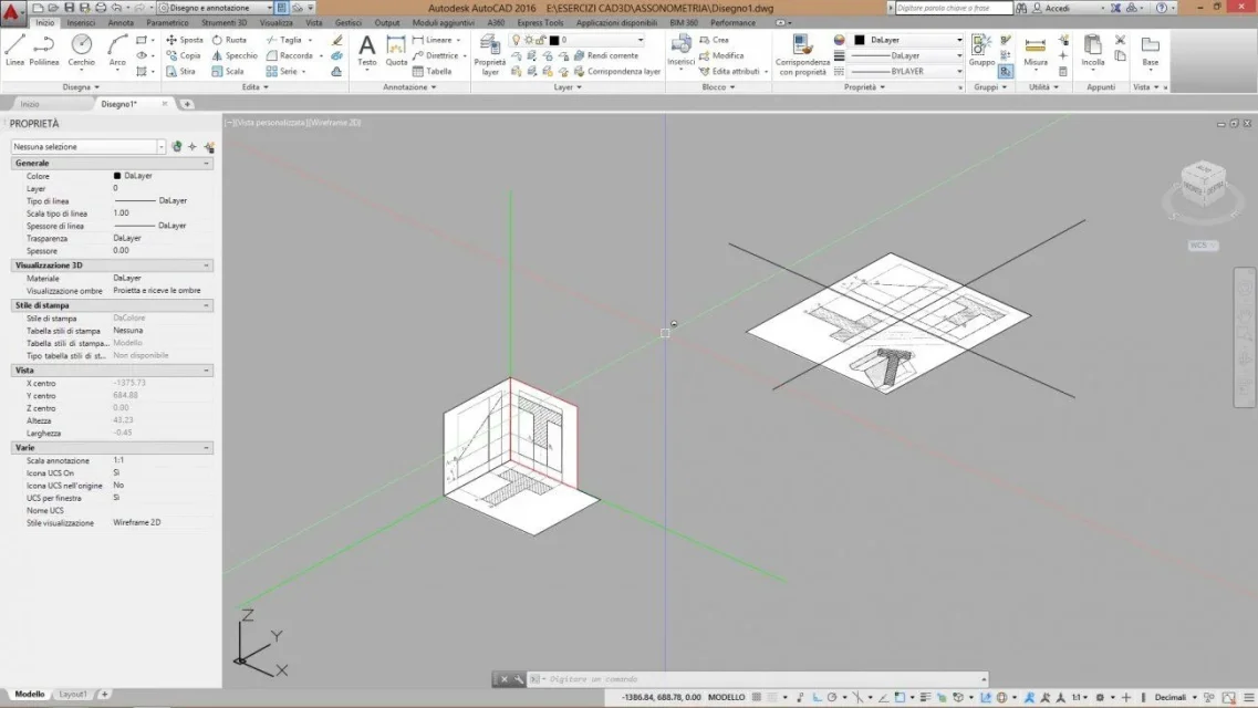
but are you sure he has to redesign it in 3d? I think you have to copy it in 2d on the envelopes as if it were handmade with paper and pen.with the command "allega" (from the menu' in the top insert-allega) brings the jpg to autocad. from the pane just entered the transparency property of the background, so you can draw lines above seeing them. draw the t with a polylinea and then extrude it according to the height of the design. at this point you have to operate a tilted cut. to simplify the process creates a flat surface quite large and tilt according to the angle of the design. for cutting use the pull command with the cutting surface option, and select the sloping surface as a cutting surface. autocad will ask you if you want to store both portions of freshly cut solid. Tell him to and delete by hand the part of solid that does not need.
and how do you do with the cobble?if he is not able to explain what he has to do and what help he needs we can also tell him how to put it on the bite and cut it by seghetto or make a plinth with kazzuola and level.
I suppose tristus trusted that the request was opened in the 3d modeling area; Unfortunately it happens that discussions are opened in the first section with a vague relevance, sometimes even with that.
It's a waste of time using a cad to get to define a solid using that method. But above all, you make students hate the program by confusing their ideas. Those things must be done by hand, like once. the cad should be taught so that the student understands it in step, not messing it up right away with those systems that are good only for paper. You can also do with cad, it's clear, but the student who approaches the cad for the first time must teach him first to master him with other exercises, and only then you can mess him up with more complex exercises.but are you sure he has to redesign it in 3d? I think you have to copy it in 2d on the envelopes as if it were handmade with paper and pen.
made in 3d are capable all....

but in that way you are only providing him with the final result, which you could well get as we explained mammals and me.at the end I had to do something like what I attached...
that made him identical spit. What did you learn from this?takeda said:thank you very much for the very detailed answers, however in the end I had to do something like what I attached (which I was kindly provided by my partner).
It seems to me that you are not able to express a well-formed request, and in our detailed comments you have been noticed. but as always you read only what you want to readtakeda said:ps. I may have mistaken the area where to put this post.
In fact in this way students learn little and begin to hate autocad immediately, defining it obsolete and Moroccan. not knowing that even more modern programs will still face the same problems. and the first unpleasant impression on autocad remains them imprinted immediately. the fault, to honor of the truth, is not of the students, but of certain professors, who teach to make 4 lines, some zoom and then tell the student "now turn this assonometry" - without having deepened how to move with the ucs, how to work on different planes etc. etc.that made him identical spit. What did you learn from this?
Then the 3d is useless. especially if you do the projections as if you use the compass on the paper.takeda has asked how the assonometry takes place, so it is clear that the procedure to follow is what would be followed by doing it on paper.
Thank you very much for the very detailed answer. However, I mention the delivery that the professor provided: "drawing, with measures to please, the orthogonal projection, the section and the monometric asonometry of the figure "t" attached "This is the process, but I repeat, the process is a little bit sleek with any cad program, which programs serve to build solids faster.
but probably the professor wanted you to be imprisoned with autocad proposing an exercise that gave students when still the computer did not exist.
Anyway, I first imported the file you posted at the beginning, I drew on it by recalculating all lines. then I rotated in 3d the two projections, selecting the lines being part of each projection and turning them in 3d with the wheel command 3d. each solid summit is defined by the intersection of 3 lines. In the example I have identified (yellow) the first summit, and then you will have to continue for each summit, so as to have the final solid uniting the summits found with a line. the result would not be a solid, but only a series of edges that define the solid. place the design too, so you can take a more detailed look.
I completely dissociate myself from what you write.with pure autocad that assonometry si si design design design (only in 2d) using cad as electronic tecnigraph