• This forum is the machine-generated translation of www.cad3d.it/forum1 - the Italian design community. Several terms are not translated correctly.

pipeline development share

  • Thread starter Thread starter xxfast
  • Start date Start date

xxfast

Guest
Hello.
excuse ignorance, but I noticed something very interesting during the quotation of a drawing.
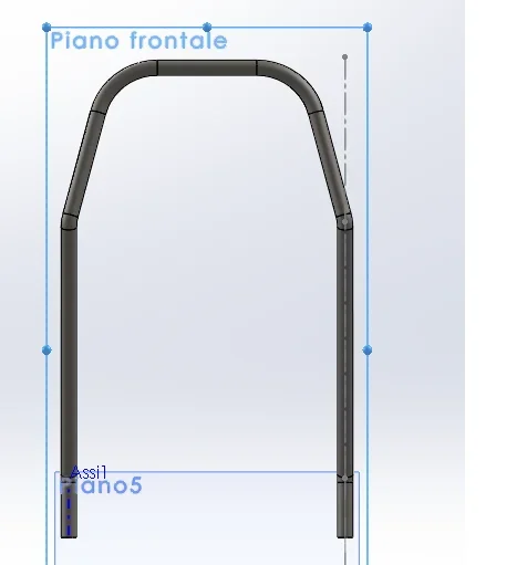
Selecting the arc loop and the 2 ends of the tube in the attached image, sw puts me a share that has the same size as the tubular development, which I previously calculated.
So in the sw quotation phase gives us development or am I saying a cabbage?
:confused:
View attachment 23465
 
Hello.
excuse ignorance, but I noticed something very interesting during the quotation of a drawing.
Selecting the arc loop and the 2 ends of the tube in the attached image, sw puts me a share that has the same size as the tubular development, which I previously calculated.
So in the sw quotation phase gives us development or am I saying a cabbage?
:confused:
View attachment 23465
that is "only" a type of quotation.
in practice touching point-point and then the arch gives you the length.

see this: http://help.solidworks.com/2011/ita...orks/videos/video_dimensioning_arc_length.htm
 
Good morning.
I should quote a tubular and have a little difficulty in doing so.
I realized that that command you were talking about gives me the length of the arc in question.
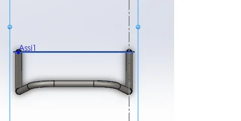
the fact is that the pipe is escaping using a 3d sketch so in one floor the bows become spline and a brothel happens.

I can't attach the file because it's not mine but I can put pictures.

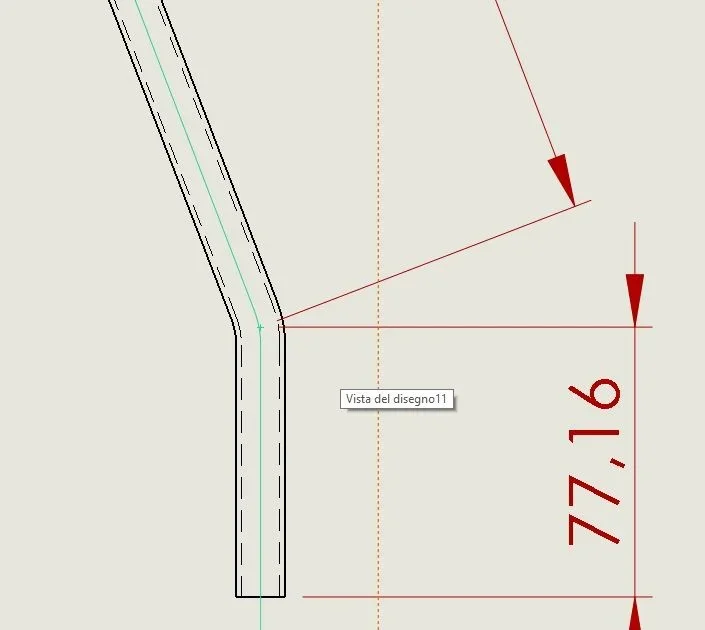
how can I quote bending rays and angles?
does not even appear the median line (short 3d) used to sweep this tubular.

suggestions?

I always thank you and apologize if I panic sometimes
 

Attachments

  • 1.webp
    1.webp
    8 KB · Views: 101
  • 2.webp
    2.webp
    3.3 KB · Views: 99
  • 3.webp
    3.webp
    9.2 KB · Views: 11
doesn't look like a fold on 3 sizes. . .
one thing you have to do is add the meeting points between the corners i.e. the virtual sharp. as in a bending design of tubes you will have to insert them into the /gi sketch /i part; then in the table you will make these sketches visible and use them to quote through the meeting points.
starting from the right floor quoti lengths of tubes* and angles; then make auxiliary views to show the orthogonal projection according to the tubes concerned. on these three views, which will be the counterpart of the front floor, you will share everything you need for construction.

* If the curves are welded, the actual length of the right section should be quoted, otherwise if it is bend curves, the meeting point of the axes must be quoted. as you see in the picture look welded curves, but it could also depend on how the part was modeled
 
doesn't look like a fold on 3 sizes. . .
one thing you have to do is add the meeting points between the corners i.e. the virtual sharp. as in a bending design of tubes you will have to insert them into the /gi sketch /i part; then in the table you will make these sketches visible and use them to quote through the meeting points.
starting from the right floor quoti lengths of tubes* and angles; then make auxiliary views to show the orthogonal projection according to the tubes concerned. on these three views, which will be the counterpart of the front floor, you will share everything you need for construction.

* If the curves are welded, the actual length of the right section should be quoted, otherwise if it is bend curves, the meeting point of the axes must be quoted. as you see in the picture look welded curves, but it could also depend on how the part was modeled
We thank you.
the part was modeled using a sweep with 3d sketch: I also attached a file time ago.
plans were created and on these floors the 3d sketch for the sweep.

Thank you again.
 
but must be a single folded pipe or curves are welded pieces?
also in 3d sketch you can put virtual sharps (in the forum you find something about their use)
 
but must be a single folded pipe or curves are welded pieces?
also in 3d sketch you can put virtual sharps (in the forum you find something about their use)
curves are welded pieces in the sense that the sweep path belongs to different planes.
 
if I go to bring back the line of half-carry on the view of the drawing concerned the point of curvature seem already there are not selectable in draft, but being the sketch 3d.tipo this alelgato
 

Attachments

then you have to quota meetings of the axes, angles and bent rays and should not see the lines of separation between straight and curved part
 
Of course it works. or better, if the curve was drawn as radius between two straights then it is automatically put to the creation of the radius
if you had taken the initiative to put the side view on the table and view the 3d sketch you would have verified the quotability through the pointsImmagine.webp
 
Of course it works. or better, if the curve was drawn as radius between two straights then it is automatically put to the creation of the radius
if you had taken the initiative to put the side view on the table and view the 3d sketch you would have verified the quotability through the pointsView attachment 46383
that you believe it or not I created the putting into the table but or sketch 3d, despite having put "show" in the file part in 2d does not appear.

By the way, it is version of sw that gives me problems even in applying the forming tools.
I need to see if I can get him to turn on another car.

I can only say thanks for patience.
 
after showing the sketch in menu view you must have activated the voice sketchesI use 2014 too and I have no particular problems. but what would be these training commands?
 
creation of forming tools such as punches for funnels.
on this pc do not have to apply the tools, on another does it without problems.

Thank you
 
Good morning, a question.
how can I read the length of the tubular developed directly from the 3d?
for example the annex?
In fact, the tube in question is developed in space, it was right to understand whether it is possible to do so in a simple way directly in the part environment.

Thank you all.
 

Attachments

without pc subhand I can tell you that in the environment part you can:
in case of sketch 3d share the route (see the forum or guide)
in case of sketch 2d make a sketch containing a line whose quota will be an equation containing the sum of the shares of the sketches of the tube (the curves will have to have the guided quota of the arc)
 

Forum statistics

Threads
44,997
Messages
339,767
Members
4
Latest member
ibt

Members online

No members online now.
Back
Top