• This forum is the machine-generated translation of www.cad3d.it/forum1 - the Italian design community. Several terms are not translated correctly.

place objects in a set

albe16

Guest
Bye to all,

I am moving the first steps with inventor and I find myself in difficulty:confused:.
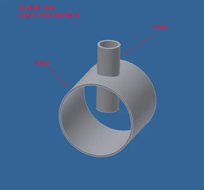
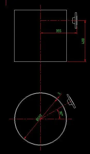
I want to insert objects (ipt) into a set (iam) and place them in certain x,y positions but I don't understand how it can specify this position.

in the specific now I want to place a cylinder on a face of an upn at a certain x,y quota but I can't do it, the only thing I can do is to put the two sides coinciding with "wine", I tried to make a 2d sketch on the face where I want to place the object by projecting the geometries but the odds turn out a hypervincle and don't let me move the object.

Can someone please help me?

I attach an image of my situation hoping it's clear.

Thank you!
 

Attachments

  • Posizionare oggetto Inventor.webp
    Posizionare oggetto Inventor.webp
    37 KB · Views: 29
I don't want to sound rude, but... try to read the window that appears when you want to insert a bond? ....


If there's no hole to place that cylinder, you need 2 constraints (3 counting the coincidence of the faces if it goes in contact)
you must bind the two-sided cylinder axis of the profile by inserting the necessary distance.
press the command to place a constraint (the basic link already selected), insert the necessary offset distance, and select the cylinder axis and the reference face
probably by entering the first bond the component will go in the direction totally opposite to the one desired, to remedy or impose the offset as negative value or reverse the selection order between face and axis
 
Meanwhile thank you for the answer!

I didn't understand the fact that I had to use more constraints, now that you told me I managed... now I have to do some practice!

Sorry if my question was banal but I do not use it for work, to work use autocad but now it is coming good sometimes inventor, so I am trying to understand at least the basic things!...

Thank you very much!
 
hi you can also use i-mates by previncolating even with i-mates of type combined your piece
But a priori I recommend you a minimum course also because with the basics you learn the logic of the program and with that you do almost everything:finger:

ps.se learns well to use inventor autocad abandon it to 90% you will use it only to open designs of ioi customers
 
You're right, I did a course... but general mooolto, when you enter the specific better understand what's behind it and what it takes! Now some progress I made it by! wouldn't you know how to help me with the subject rotating speech? I'll explain. .
I placed a flange on a tube in the position where I want, the flange does not move but can rotate along the axis...how do I to give an angle to the position of the flange holes compared to the axis of the pipe?
flangia.webp
 
The quickest thing would be to bind the axis of one of the holes with one of the tube planes if you don't have to adjust the angle.
if you want to adjust it you have to bind a flange plane with one of the tube planes something so more or lessangolo piani.webpIf the original plans don't suit you (depending on how you built the piece) you have to create one, the quickest thing should be doing a board on two of the holes and then use them to make a plan.
 
...how do I do to give an angle to the position of the flange holes compared to the axis of the pipe?
advice: when you do the sketch, always try to draw in a "symmetrical" way with respect to the point of origin, so when you go to assemble the parts you can take advantage of the plans/axis of origin without having to create a thousand thousand thousand... :finger:
 
thanks for the precious suggestions that have given its fruits! !

I am now in a condition in which, wishing to draw a tube with a branch (tube tube tube) I cannot proceed.
what I would like to do is within a .iam set to create the pieces of pipe cut and worked as it serves so that the various solids have the properties of the tubes to be exploited later for extraction materials etc.
I tried in 3 ways,
starting from surfaces, I managed to create the shaped tube piece (but here the object is a solid and has no information on what it is)
starting from solids, I'm in the condition where I can't split the cut pipe, how do we proceed?
Starting from a set and entering from content center, is what I would like to do so that I also have information about objects, but I don't understand how to work the 2 solids. :confused::confused:

Can you help me?

Thank you!:biggrin:
 

Attachments

  • assieme.webp
    assieme.webp
    14.2 KB · Views: 10
  • SOLIDO.webp
    SOLIDO.webp
    6.1 KB · Views: 11
  • SUPERFICI.webp
    SUPERFICI.webp
    9.5 KB · Views: 9
I honestly don't think I actually understood the problem,
If it's just like making the shaped cut on the small tube..... once placed where it serves I would project the profile of the bigger tube on a sketch made on a piece plane to cut and a nice extrusion for removal of material

if instead you need to simulate the cut of the tool and to have usable also the tube mozzicone cut off..... I don't think of anything else, I've never had to draw scrap pieces.
 
go together, open a component, then copy object, select the surfaces you are interested in, then with the divided part,
work all to please!!
 
I am in the condition of having to place a flange oriented to the axis with a certain distance from the virola.
with very simple autocad move the flange and then rotate over the center, but with inventor it is going crazy.

Can someone tell me how to bind the flange to make it at a certain distance and at a certain angle? :confused:
 

Attachments

  • Flangia.webp
    Flangia.webp
    13.1 KB · Views: 42
taking for granted that the plans of origin of the parts are also the plans of symmetry:

plate of origin binding flange coincident with virola axis
stranded angular flange of virola origin (x-x)
concisely bound flange with boh! distance to virola (y-y) plane of origin
binding flange face coincides with distance l from virola axis


This is what I would do, there are still other options.

Say hi!
 
Thank you for the answer, but I'm not very clear.
table of origin flange which?
the plans of virola origin are xy - xz - yz, x-x and y-y I do not see them among the options.:confused:
 
Thank you for the answer, but I'm not very clear.
table of origin flange which?
the plans of virola origin are xy - xz - yz, x-x and y-y I do not see them among the options.:confused:
Yes, I wrote x-x quickly without looking. . However, I don't know how your stuff is done and so I can't explain to you in detail, when you step on top of your browser's floors, they light up and choose the right one. as I said because the game functions as described plans of origin and symmetry must coincide.
 
to me it is not clear the procedure, because trying to orient the flange it rotates on itself and not on an arc regarding the virole center.
My request is just an example to understand the procedure, I try to attach an image to better explain what I would like to do.
what I would do with autocad and give first linear coordinates and then the corner, but with inventor obviously it is not so.
 

Attachments

  • vista.webp
    vista.webp
    9.5 KB · Views: 34
what I would do with autocad and give first linear coordinates and then the corner, but with inventor obviously it is not so.
learned, you have to use inventor and not think about autocad otherwise you lose only time since one with the other does not have to share.
use the pairing controls by choosing the geometric entities you need so you can orientate the flange as you want, as you know how it has to go. plan-plans, faces-planes, axes, axes-bords etc. you only have the embarrassment of choice. works so with any cad3d
 
sacred as said by marcof: the inventor coupling system has nothing to do with autocad. in autocad positions the drawings in space starting from the assumption that then there remain until you voluntarily move them; in inventor colleagues by means of constraints the various components so that they have the degrees of freedom desired. for my experience binding well is an art that you learn with time and effort. Try with the inventor tutorial so you get a more precise idea.
 
you are totally right, autocad with inventor does not hit anything!... only that such a trivial thing is turning out to me an impossible venture!
Couldn't someone kindly draw me what I posted above so I can understand the constraints?
I did several tutorials but I never found this problem... .
 
you are totally right, autocad with inventor does not hit anything!... only that such a trivial thing is turning out to me an impossible venture!
Couldn't someone kindly draw me what I posted above so I can understand the constraints?
I did several tutorials but I never found this problem... .
  1. flange-axis rear face: distance bond set at 355 mm
  2. a plan of the virola-a plan in axis with flangs: angle bond of 30°
  3. flange-face axis of virola head: distance bond of 400 mm
I don't understand what difficulties you're facing. look at the geometry of the virola, look at the geometry of the flange and choose which entities must have distances and angles you need. The rest falls.
 

Forum statistics

Threads
44,997
Messages
339,767
Members
4
Latest member
ibt

Members online

No members online now.
Back
Top