• This forum is the machine-generated translation of www.cad3d.it/forum1 - the Italian design community. Several terms are not translated correctly.

problem creation hole on crank pin.

  • Thread starter Thread starter Richart
  • Start date Start date

Richart

Guest
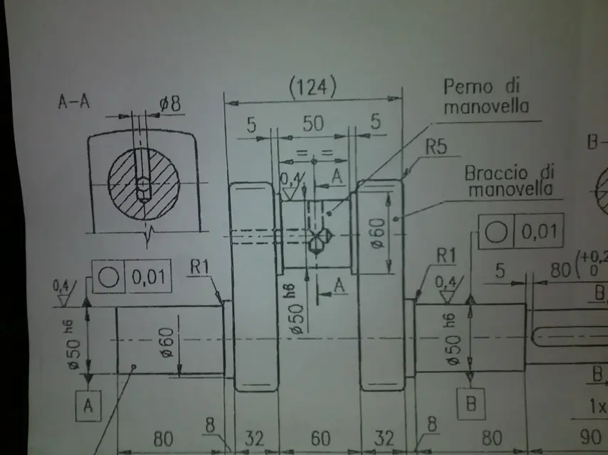
hi guys, I made the set of a counter pin with a "hand crank to elbow" now I should be able to pierce the crank pin like the photo, but I can't because sw doesn't recognize me that part like a surface or plan. I also can't use simulationxpress because the function is not supported overall, while in the part it does not recognize any solid element.

I attach the set, the part created by the set, and the photo of how the hole should be created.

appearance your clarifications and

thank you all in advance!

p.s. why is there always a visible sketch in the axieme?
 

Attachments

Hi.

I have not yet installed 2011, but if you try with creation wizard holes you do quietly. at most you will have to draw one - two lines for construction to bind the holes.
Keep in mind that you can drill even from a plan.
 
hi guys, I made the set of a counter pin with a "hand crank to elbow" now I should be able to pierce the crank pin like the photo, but I can't because sw doesn't recognize me that part like a surface or plan. I also can't use simulationxpress because the function is not supported overall, while in the part it does not recognize any solid element.

I attach the set, the part created by the set, and the photo of how the hole should be created.

appearance your clarifications and

thank you all in advance!

p.s. why is there always a visible sketch in the axieme?
that particular is composed only of surfaces, it is not a solid.
How did you do that?
Did you care?
 
that particular is composed only of surfaces, it is not a solid.
How did you do that?
Did you care?
here is the process of creation.

I started creating the sketch of the counter pin and then extruded it using the extrusion function in revolution. I saved the file as part.

I then created the crank sketch to elbow and extruded it, I always saved it as part.

I later did: file----> new----> set and I created the pin set and crank, concentricly mating them. of this together I saved a file as together (*.sldasm) and one as part (*sldprt). both are visible in the *.zip file previously posted.

I also place the archive with the relevant parts with which I created the aid.


:smile:
 

Attachments

I have not downloaded yet and looked at the files..

but in the meantime:
Why do you do a set when that tree is (at least it seems) "monolithic", so to build (and model) in one part?

unless it is like certain motorcycles (the 2t on all) with the pins forced to press in the flyers.. but from the design I wouldn't say.

greetings
Mar
 
I have not downloaded yet and looked at the files..

but in the meantime:
Why do you do a set when that tree is (at least it seems) "monolithic", so to build (and model) in one part?

unless it is like certain motorcycles (the 2t on all) with the pins forced to press in the flyers.. but from the design I wouldn't say.

greetings
Mar
from the design however are indicated both "pin" and "arm" of crank as if they were two distinct parts and assembled later.
Now, even if so, no one forbids to model it in one part and possibly put notes on the drawing.. .

Hi.
p-h
 
here is the process of creation.

I started creating the sketch of the counter pin and then extruded it using the extrusion function in revolution. I saved the file as part.

I then created the crank sketch to elbow and extruded it, I always saved it as part.

I later did: file----> new----> set and I created the pin set and crank, concentricly mating them. of this together I saved a file as together (*.sldasm) and one as part (*sldprt). both are visible in the *.zip file previously posted.

I also place the archive with the relevant parts with which I created the aid.
:smile:
huuummmm now I understand why the original parts were missing in the previous set, I bet you renamed the windows files?
In fact, he told me that the id of the file was not that...
in the file you posted now, there are 2 parts, although I don't know how you will mount them, since the hole to accommodate the tree is on the same axis as the foot of the biella... But anyway, that's not your question. (besides the tree is short, it does not cover the rotary masses of the crank)
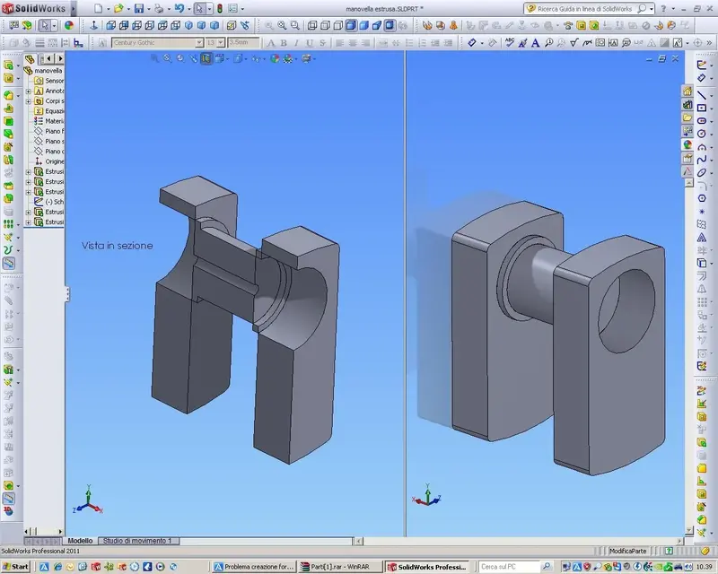
also the handle is held together by thickness 0 (zero), see attachment.
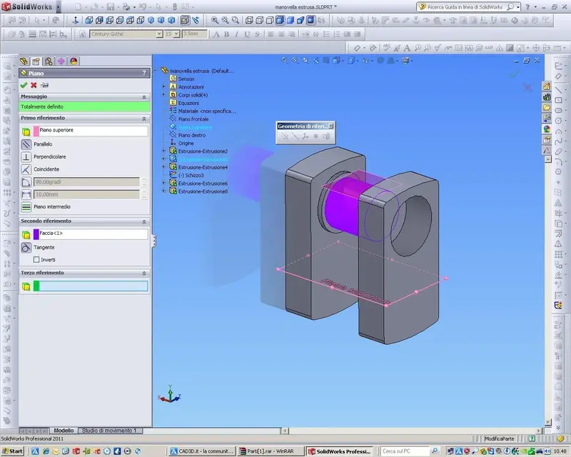
to be able to pierce any curved entity, create a plan to use
as a starting point for the hole, in fact.
to create a plan: instrument "reference geometry", selections "plan",
indicate the upper-parallel plane, the cylindrical-tangent face and the game is made.

as already written by someone else, that tree lends itself to a design
of a unique body, in fact in your scanned design, there are no indications for
the assembly through interference.
 

Attachments

  • Vista in sezione.webp
    Vista in sezione.webp
    113.2 KB · Views: 26
  • Piano.webp
    Piano.webp
    114.9 KB · Views: 13
to be able to pierce any curved entity, create a plan to use
as a starting point for the hole...
Yes, but also with a 3d sketch, without "support" plans.
...while in the part does not recognize any solid element.
Sure, if you used that file saved in igs (who knows why? ).
There are no solids because the iges creates surfaces, and your piece if you look at it is just an "empty skin".
save in .sldprt. indeed, it models all directly in part unique:View attachment ALBERO MOTORE.rarHello
marco
 
I'll tie your crank with the holes.
apart from your doubt, the fact that you could better exploit the main plans and some other small detail, I compliment you for the method used.
Layout sketch is a technique that use few in classical modeling and that I love to use when it is possible.
 

Attachments

I'll tie your crank with the holes.
apart from your doubt, the fact that you could better exploit the main plans and some other small detail, I compliment you for the method used.
Layout sketch is a technique that use few in classical modeling and that I love to use when it is possible.
Forgive me for contradicting you.. (apart from the file I already posted to him, but 2 solutions are better than one :biggrin:), but I wouldn't really say that the richart tree is "well modeled", graphically and above all mechanically speaking. apart from that it is obvious to be monolithic from the full (then unique part), but also wanting to make it together of components, you would build the counter pins in that way? doing a part with the tree cut in two?? one of the first rules would be to follow as far as possible the real method of production process (working cycle), reasoning as if I had the "pieces in hand".
There is no definite sketch that it is one, the layout in space 3d is random with the "note" plans of the "stort" tree at home. the crank button is flying suspended in the air.. etc. etc. (I would like to see the tables :smile:).
I don't think it's the case of complimenting him (sorry richart, it's not to criticize you. I understand that you are in the first weapons with swx, but this is pure and simple question of mechanics and technical design. better to identify and correct errors immediately.. Wow, from what I understand you're about to become an engineer and these are very basic exercises, unless you want to be ironic.
and then where did you see he used the lay out sketch? ?

greetings
Marco:smile:
 
Forgive me for contradicting you.. (apart from the file I already posted to him, but 2 solutions are better than one :biggrin:), but I wouldn't really say that the richart tree is "well modeled", graphically and above all mechanically speaking. apart from that it is obvious to be monolithic from the full (then unique part), but also wanting to make it together of components, you would build the counter pins in that way? doing a part with the tree cut in two?? one of the first rules would be to follow as far as possible the real method of production process (working cycle), reasoning as if I had the "pieces in hand".
There is no definite sketch that it is one, the layout in space 3d is random with the "note" plans of the "stort" tree at home. the crank button is flying suspended in the air.. etc. etc. (I would like to see the tables :smile:).
I don't think it's the case of complimenting him (sorry richart, it's not to criticize you. I understand that you are in the first weapons with swx, but this is pure and simple question of mechanics and technical design. better to identify and correct errors immediately.. Wow, from what I understand you're about to become an engineer and these are very basic exercises, unless you want to be ironic.
and then where did you see he used the lay out sketch? ?

greetings
Marco:smile:
Marco,
I downloaded his file to put holes in it.
I don't know whether the piece should be monolithic or multiple pieces and not that the odds are missing, I know that someone else would have thought of it.
I complimented him for the method used, the layout method, because few use it, taking into account that it is a novice.
for me the sketch of layout is not only at the level of assembly that pilots the parts, but also in the environment part, that is a master sketch or sharing that pilots some functions.

I took a look at your model and for me it is badly shaped, especially by one who is moderator of the forum solidworks.
none of the operations you have performed has a logic.
no logic to get a simple, fast model in the recalculum and that performs as you affirm, working sequence.
definitely the method of the novice and better than that of the moderator.
 
Marco,
I downloaded his file to put holes in it.
I don't know whether the piece should be monolithic or multiple pieces and not that the odds are missing, I know that someone else would have thought of it.
I complimented him for the method used, the layout method, because few use it, taking into account that it is a novice.
for me the sketch of layout is not only at the level of assembly that pilots the parts, but also in the environment part, that is a master sketch or sharing that pilots some functions.

I took a look at your model and for me it is badly shaped, especially by one who is moderator of the forum solidworks.
none of the operations you have performed has a logic.
no logic to get a simple, fast model in the recalculum and that performs as you affirm, working sequence.
definitely the method of the novice and better than that of the moderator.
in fact the layouts should be used well not as he used them... he went to do
a concentric hole to the biella pin, if this is to use well the layout... Do you!
At the same time it failed to create the interference housing holes for the rotation axis. . . .
Did you see the image I posted??
Tell me if a mechanical component is conceivable like that.
http://www.cad3d.it/forum1/attachment.php?attachmentid=19757&d=1299318655
 
in fact the layouts should be used well not as he used them... he went to do
a concentric hole to the biella pin, if this is to use well the layout... Do you!
At the same time it failed to create the interference housing holes for the rotation axis. . . .
Did you see the image I posted??
Tell me if a mechanical component is conceivable like that.
http://www.cad3d.it/forum1/attachment.php?attachmentid=19757&d=1299318655
I wonder if you understand what I write.
I praised his method to use only one sketch to produce the piece, not the design choice.
the improvements there might be, but compared to what I saw do as beginners and not, the choice made is certainly the best.
the method of shared sketch is great in this case...and I repeat, I speak of method, everything else is not my business.
 
...no one of the operations you performed has a logic.. .
Maybe you don't see her...:frown:

that could only be one of the methods to execute it. made especially to make him understand the "real" processes, starting from the billet to work (although those trees are first printed and then worked to measure the machines, but apart from the "full" of departure operations change little).

greetings
Mar
 
I wonder if you understand what I write.
I praised his method to use only one sketch to produce the piece, not the design choice.
the improvements there might be, but compared to what I saw do as beginners and not, the choice made is certainly the best.
the method of shared sketch is great in this case...and I repeat, I speak of method, everything else is not my business.
for me he was not conscious at all that he was creating a sketch of layout:biggrin:... that's all.
Beginners (no offense to anyone, I was also myself) tend to use the 3d as a 2d... at first, from there the impression of the layout...:biggrin:
 
the method of shared sketch is great in this case.
even this statement can be very questionable
...and I repeat, I speak of method, everything else is not my business.
but it is a matter of a future engineer, to which perhaps it would be better to explain other things and help him in mistakes not only regarding the cad.

greetings
Mar
 
I'll tie your crank with holes.
apart from your doubt, the fact that you could better exploit the main plans and some other small detail, I compliment you for the method used.
Layout sketch is a technique that use few in classical modeling and that I love to use when it is possible.
multibody?...:biggrin:
 
Maybe you don't see her...:frown:

that could only be one of the methods to execute it. made especially to make him understand the "real" processes, starting from the billet to work (although those trees are first printed and then worked to measure the machines, but apart from the "full" of departure operations change little).

greetings
Mar
If you wanted so much modeling following a 'real' working logic, you shouldn't have even started with such a block.
biella is a fusion and modeling it with shared sketches is the optimal solution.
then put in another part and do the work, which I would not have done like you anyway.

If you give modeling advice, you must insert an example clarifying.
for the designer's advice, it is at discretion in this forum, since we talk about cad solidworks.
the design forum is another.
 
I downloaded his file to put holes in it.
In fact.. and that axial hole you did it for good (and here I am ironic.. go see you again, maybe you were distracted).
biella is a fusion and modeling it with shared sketches is the optimal solution.
.
Perhaps you confuse, this is a motor tree and not the biella of the other thread.
and then if you had read everything (even you quoted it) you would have seen that first I said that the trees are first printed (the best) or merged and then worked. and what feature approaches more to such processing starting from a full or outburst with overmetal?

Then, as you seem to be a lover of statistics and "read" operations (and this is good), try to see the times of total reconstruction.. and that's not even complete.

greetings
Marco:smile:

try to smile once..:biggrin:
 
Last edited:
In fact.. And that axial hole you did for good.

Perhaps you confuse, this is a motor tree and not the biella of the other thread.
and then if you had read everything (even you quoted it) you would have seen that first I said that the trees are first printed (the best) or merged and then worked. and what feature approaches more to such processing starting from a full or outburst with overmetal?

Then, as you seem to be a lover of statistics and "read" operations (and this is good), try to see the times of total reconstruction.. and that's not even complete.

greetings
Marco:smile:

try to smile once..:biggrin:
I just praised his method, better his than yours.
I would have always done the same method as the shared sketch.

Do you know why I put the statistics?
have meaning for you?
Am I an index of something?

I know you know and you know how important they are to improve/you and limit problems of all kinds in part and together environment.
 

Forum statistics

Threads
44,997
Messages
339,767
Members
4
Latest member
ibt

Members online

No members online now.
Back
Top