• This forum is the machine-generated translation of www.cad3d.it/forum1 - the Italian design community. Several terms are not translated correctly.

reducer, 1 tree

  • Thread starter Thread starter maverick_87it
  • Start date Start date

maverick_87it

Guest
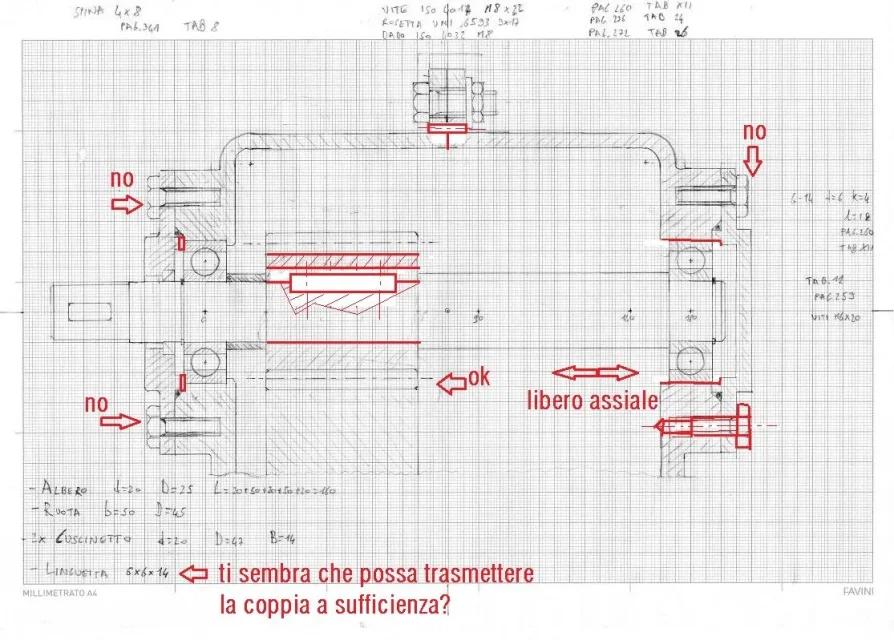
Hello everyone, I've been following you for a while, I'm also struggling with the design of a reducer, I just need the 1 tree and I have to do it by next week, so I want to show you a little this together that I came to see if the design as it is done can go.
on the shaft is calettata via tongue a toothed wheel with straight teeth, I am not sure on the positioning of the quarry and I perplexed (even after seeing 3 manuals) on how the wheel should be drawn, including the coupling with the second wheel.
Are the bearings well bound?
in the upper part I was told to insert a pin... really serve? If yes, I will certainly have to increase the thickness of the flange.

View attachment riduttore mio.pdf
 
we are hurt then.. ..because if you're a junior mechanic engineer it means you've done several tests that should allow you to have the right knowledge.

the two bearings are blocked both on the inner ring and on the outer one (but badly on the outside with the cover). representation hollow tongue incorrect, both in the tree but above all in the gear (that square of the tab is embedded by magic??? ? )

the thorns that join the carcass are supposed immersed in a huge hole... but how do you think they are there? and how do you infiltrate them?

representation screws of the lids screwed in the carcass are wrong.

the cover that holds everything can not have all the parcel surfaces so by magic, so it takes a shaving ring or swivel seals
 

Attachments

  • riduttore mio_1.webp
    riduttore mio_1.webp
    172.2 KB · Views: 73
we are hurt then.. ..because if you're a junior mechanic engineer it means you've done several tests that should allow you to have the right knowledge.

the two bearings are blocked both on the inner ring and on the outer one (but badly on the outside with the cover). representation hollow tongue incorrect, both in the tree but above all in the gear (that square of the tab is embedded by magic??? ? )

the thorns that join the carcass are supposed immersed in a huge hole... but how do you think they are there? and how do you infiltrate them?

representation screws of the lids screwed in the carcass are wrong.

the cover that holds everything can not have all the parcel surfaces so by magic, so it takes a shaving ring or swivel seals
hello, that was just a draft and in fact those were the doubts I had.
I changed the screws because the hole was drilled so they were very badly represented:)
I'm not sure if they're okay.
I replaced it with a higher pin because it was better accessible.
the tab on the tree I had taken another representation of another drawing but then the prof made it change, at the end I drew it like you, for the sizing of the same calculations are accurate, controlled and rechecked :)
the two lids dx and sx separated from a seal.
But now I do not know if I can put the final design because I have it in the big sheet that I have to deliver :) I hope it goes well as I have corrected :)
 
Mechanicalmg I hoped for your most timely answer:smile: You told me the same thing about the professor, in fact, I did another sketch and now here's the final one.
the time is over, Monday I have to deliver and as promised here is the final design, I hope it is not perfect but that at least there are no gross errors :rolleyes:
I did not draw the second toothed wheel to straight teeth because on the first the prof had made me understand that it was not drawn in that way: but I threw a thousand dispensers and 3 manuals and you seemed to have said ok so I left one in that way and stop:confused:
IMG_0371.webp
 
Thank you so much!!
I'll try to correct him! :wink:
on the toothed wheel I had hypothesized a 2.5 module, I could choose 2 and I got a 45 wheel instead of 50 but now it is too late to remake everything.
however the tab has been sized for a couple of 25 nm with safety coefficients on the material and the load pairs respective to 1.5 and 2, I found a dimension however in line with the other of my colleagues, however then recalculated for safety
 
I have done two accounts and I have seen that the tab is ok for 25nm to transmit but I still remain very perplexed on the gear because if you have a wheel in 42crmo4 hardened to induction you have a specific pair of 8n*m/mm therefore the band width is 4 mm to stay wide, so you can very well change module and get down to have a 15~20 mm ingrain belt and possibly go down a lot.
Linguette UNI 6604_1.webp42CrMo4_HERTZ_Z20_1.webp42CrMo4_lewis_1.webpHowever you do the verification according to one 8862 or second iso 6336 and you will see that you are overflowing.
 
Great!
Where did you find those charts?
However I send you in mp the procedure used for the dimensionalizations, I do not know that maybe I also cover the :tongue:
 
Great!
Where did you find those charts?
However I send you in mp the procedure used for the dimensionalizations, I do not know that maybe I also cover the :tongue:
I made the charts. I did them with excel because I was tired of using the calculation program and to dimensional flight is fine. clearly for particular applications I still use the dedicated program since it makes me all the corrections of the profiles and wheels of all types.
However if you do the inverse formulas of lewiss and pitting revenues the pair with m=1 and you have the graphs.
 

Forum statistics

Threads
44,997
Messages
339,767
Members
4
Latest member
ibt

Members online

No members online now.
ciao
Back
Top