• This forum is the machine-generated translation of www.cad3d.it/forum1 - the Italian design community. Several terms are not translated correctly.

request edit .step file

  • Thread starter Thread starter AutostuDent
  • Start date Start date

AutostuDent

Guest
Although I was granted by autodesk education to use from autocad 2014 until autocad 2016 for 3 years, having as operating system seen I find myself unable to use any, at least until next formatting and change s.o.
as I need to make 3 small changes on a .step file (it is about to vary 2 rays) within a short time, I wanted to know if there was some pious soul that could help me in this sense?
 
Although I was granted by autodesk education to use from autocad 2014 until autocad 2016 for 3 years, having as operating system seen I find myself unable to use any, at least until next formatting and change s.o.
as I need to make 3 small changes on a .step file (it is about to vary 2 rays) within a short time, I wanted to know if there was some pious soul that could help me in this sense?
post the zipped file, indicates which roundings change and what value you need.
 
@maxopus
Hi, I had some problems with compressing files, if there were any problems I can post them without compression.
(I hope there are no definition quality peritis after compression)
having made turn autocad 2014 on a xp with processor e3200 (simil post-pentiumiv) without dedicated video card... I limit myself to a no-comment... :36_6_1:

in case there is someone willing to do this great courtesy, I need:
-> close the entire slit (1a) present on the component.
-> reduce cylinder diameter (2a) to 14mm (concentric)
-> increase the diameter of the 2 cylinders "cavi" (1b) of 1mm concentricly (there must be a diameter of about 9mm in conclusion)
Obviously using the wireframe or x-ray view you will notice the conformation from you.
all about the 2 .step files that have these elements in common, the picture below is referred to the x_motor component as reference.
View attachment 421Vista A.webpVista B.webp
 
the files you posted have different problems, they lack different surfaces in correspondence of some transitions on the roundings, so they are not solid.
I try to solve... but with which cad you exported?
 
in all sincerity I do not remember that version is installed in infographic classroom, also because the logo was slightly different from autocad 2014 that I installed on xp.
is the problem solved?
stefanobruno thank you so much as I return home tonight I will try to open them even if I see it hard, the bad weather forced me to change power supply and burned 1gb of ram
 
in all sincerity I do not remember that version is installed in infographic classroom, also because the logo was slightly different from autocad 2014 that I installed on xp.
is the problem solved?
stefanobruno thank you so much as I return home tonight I will try to open them even if I see it hard, the bad weather forced me to change power supply and burned 1gb of ram
but then it is possible to convert them also to .stl?
As for the open lines, did you refer to the x_idler file? because that component is formed by 3 pieces, the knob the central block and a third removable, which I should have placed vertically in the .stl
(excuse me having clear what it was for granted that they were known data)
If you're referring to something else with open surfaces, could you please let me know?
 
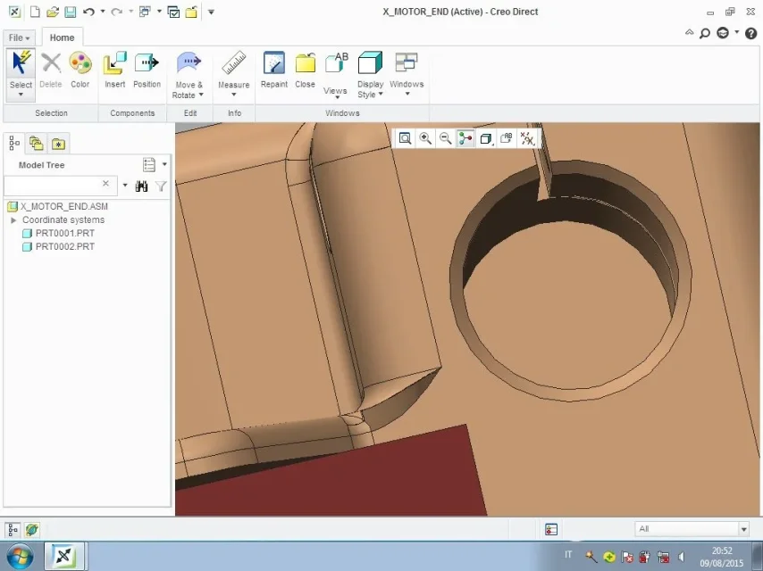
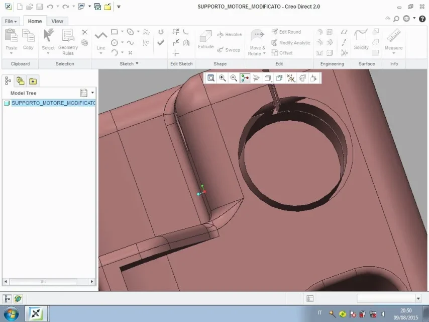
to me are good ones made with autocad while those made with inventor do not look at the pictures in comparisonstep-autocad.webpstep-inventor.webp
 
I remain everything, learning with creo direct 2 is curious, after careful analysis I miss many surfaces also with step autocad, the curious thing is that there are surfaces on step autocad that are present on step inventor while lacking surfaces on step inventor that are present on step inventor
@autostudent
fusion 360http://www.autodesk.com/products/fusion-360/overview
 
in the coming days I will try to export a step of creo parametric and see how it is read from the other cad.
 
autocad step gives me errors also on rhino 5 and solidworks 2013,ergo is all fault of autocad:wink:
 
I'm not getting it.
is roar therefore a mistake due to the modification made by stefano? I was convinced that I had realized it with inventor after reading the last antecendent messages.. But now after reading the answer number1 I think it was used autocad mechanical (is it possible? ..a certainty I will have at the beginning of September)
anyway I need to print the component in 3d, so a missing surface I think makes a difference in .stl conversion or not? :36_1_31:
 
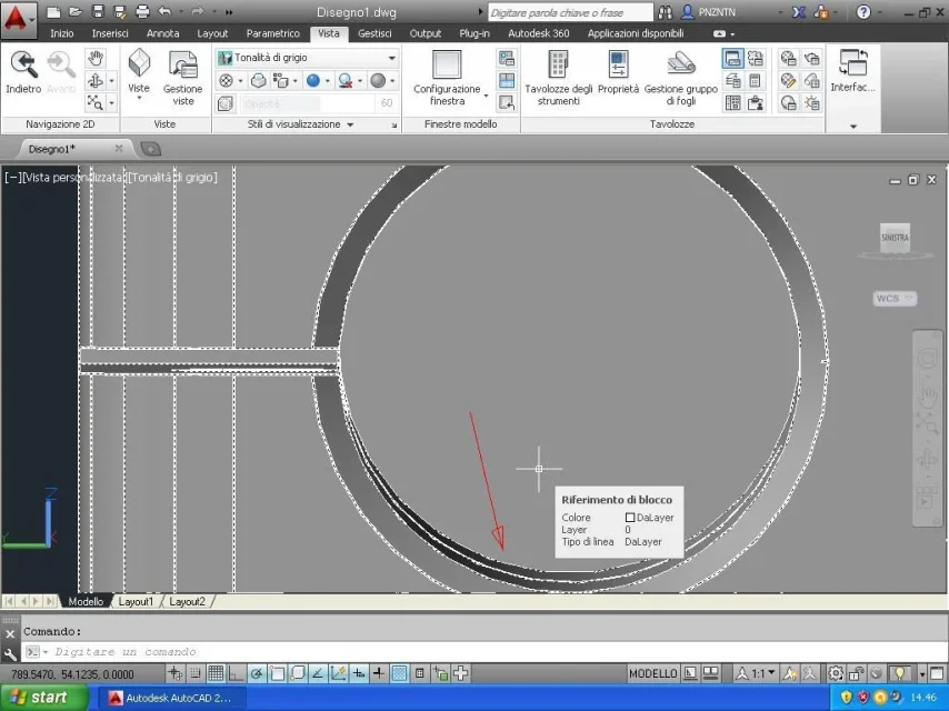
I also found some opening in the crazy support file (modified) as from photo on autocad 2014.
Is everything solved?
Immagine2.webp
 
I did a test with the files I sent, I opened them with rhino and they are not open edges.
How do you open the stp in autocad?
 
I did a test with the files I sent, I opened them with rhino and they are not open edges.
How do you open the stp in autocad?
I opened your steps with rhino 5 and many transitions on the fillets have problems, which I eliminated by recreating the surfaces with patches.
did this I exported the steps and I reopened them in pro/e 2001 that read them as solids.
I think I create shouldn't have trouble reading them now.
 

Attachments

I'm not getting it.
is roar therefore a mistake due to the modification made by stefano? I was convinced that I had realized it with inventor after reading the last antecendent messages.. But now after reading the answer number1 I think it was used autocad mechanical (is it possible? ..a certainty I will have at the beginning of September)
anyway I need to print the component in 3d, so a missing surface I think makes a difference in .stl conversion or not? :36_1_31:
emm... "After reading the answer number1" or my answer, should I deduce that it was referring to this?? ?http://www.cad3d.it/forum1/threads/...are-compatibile-per-vista?p=365351#post365351
 

Forum statistics

Threads
44,997
Messages
339,767
Members
4
Latest member
ibt

Members online

No members online now.
Back
Top