• This forum is the machine-generated translation of www.cad3d.it/forum1 - the Italian design community. Several terms are not translated correctly.

request edit .step file

  • Thread starter Thread starter AutostuDent
  • Start date Start date
I opened your steps with rhino 5 and many transitions on the fillets present problems
I don't understand. I'm still having trouble.
I attach the rows of rhino5, obtained from the stp converted by inventor and not further treated.

 

Attachments

I don't understand. I'm still having trouble.
I attach the rows of rhino5, obtained from the stp converted by inventor and not further treated.
I'm sorry. I'll explain.

importing your steps into rhino there are no problems, except that only "holy support" is recognized as a valid closed polysurface (so a solid ).
the other piece "motor support" is recognized as valid but not closed polysurface (it is not a solid).

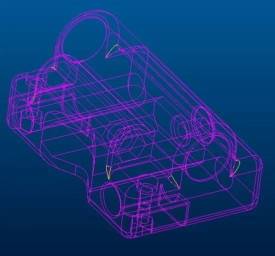
When importing your steps in pro/e 2001 problems occur on both pieces and in the same points, see the image highlighting the edges (yellow) with shredding errors that cause the unclosing of the surface union.

I think it has to do with the absolute tolerance set in the cad with which the pieces were originally made.
 

Attachments

  • stefano.webp
    stefano.webp
    44.1 KB · Views: 29
the other piece "motor support" is recognized as valid but not closed polysurface (it is not a solid).
I confirm, he says that to me too.
in the analysis of open edges, rhino5 does not report any.
the rhino file "motor support ", in inventor is opened as surface, sign of the presence of open edges.
the open edges however find them in the thread, made with a helid that, probably, in the various conversions has deteriorated.
the fittings that pro/e sees as corrupt, inventor digested them as fresh water.
 
therefore with the modification made by marius should be readable on any type of program?
@marius the files you have corrected I guess are those edited by stefano?
 
therefore with the modification made by marius should be readable on any type of program?
I would not be so optimistic:)

the interpretation of what's in a step file depends on both the program that creates it and what reads it.
But trying doesn't cost anything... Let us know
@marius the files you have corrected I guess are those edited by stefano?
That's right. .
 
Last edited:
I confirm, he says that to me too.
in the analysis of open edges, rhino5 does not report any.
the rhino file "motor support ", in inventor is opened as surface, sign of the presence of open edges.
the open edges however find them in the thread, made with a helid that, probably, in the various conversions has deteriorated.
the fittings that pro/e sees as corrupt, inventor digested them as fresh water.
Unfortunately or fortunately autodesk does not have the monopoly of the sw cad, no one would discover the faults of autocad in working in 3d
p.
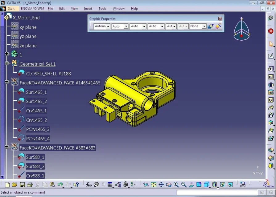
I knew the facekos that appeared to me opening the two xmotorend steps and modified motor support with catia
 
Unfortunately or fortunately autodesk does not have the monopoly of the sw cad, no one would discover the faults of autocad in working in 3d
p.
I knew the facekos that appeared to me opening the two xmotorend steps and modified motor support with catia
xmotorend.webpsupportomotoremodificato.webp
 
I'm sorry. I'll explain.

importing your steps into rhino there are no problems, except that only "holy support" is recognized as a valid closed polysurface (so a solid ).
the other piece "motor support" is recognized as valid but not closed polysurface (it is not a solid).

When importing your steps in pro/e 2001 problems occur on both pieces and in the same points, see the image highlighting the edges (yellow) with shredding errors that cause the unclosing of the surface union.

I think it has to do with the absolute tolerance set in the cad with which the pieces were originally made.
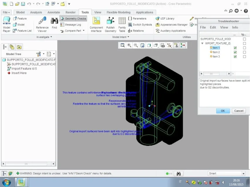
the checkup that makes me create is more beautiful:
firstsupportofollemodificato-checkcreo.webpsupportomotoremodificato-checkcreo.webpGood mariuss:finger:
now I catch and I grow heartily thank you:
 
but it is not that here pieces are too simple for creocatiaproe, so the prog. gets tired and takes under the leg easy fittings waiting for the super complex ones? :36_1_18:
 
just another question you can convert via autocad 2014 step to .stl? (with a resolution of 0.01mm on "layer"? )
possibly yes, how?


edit
or better for a good 3d print with 0.1mm resolution which recommended value to use for facetres for proper conversion?

a'riedit
wanting to place the object in the positive octant so that it is vertical and perpendicular to the plane, there is any procedure to follow rather than go so "to the eye" ?
 
Excuse me if I resume the discussion,
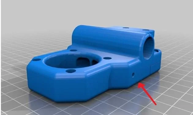
only after printing the piece in 3d I realized that during conversion to .stl of files modified by marius, a threaded hole is literally lost, visible in this screenshot of how it should be.
I used facetres set to: 10
I set maximum smoothness: 4 (in the mesh setup)
I used the command: stlout (here might have been a problem? ! )
in fact immediately after I was asked to select the object, and remained the open row.. I wrote yes in that line and passed to the next,
where he asked me if to save in binary file and I did yes (s) also they... (maybe I should have given the final selection command??? What is that? )

However I attach the image of the hole that has not been converted.
(the basic polygons are set on parallelepiped with all values 3) (using always autocad 2014)
 

Attachments

  • Immagine.webp
    Immagine.webp
    15.9 KB · Views: 28
Bye to all,

I need to change the format of a file from .sldprt to .step to be able to insert it into a layout.
Unfortunately I don't have solidworks software.
Can anyone help me?

How do I post the file link on this blog?
 
I have the converted stp, if you send me a private message with your email address and I send you a message with wetransfer.

Bye.
 

Forum statistics

Threads
44,997
Messages
339,767
Members
4
Latest member
ibt

Members online

No members online now.
Back
Top