• This forum is the machine-generated translation of www.cad3d.it/forum1 - the Italian design community. Several terms are not translated correctly.

s.e. v17: citation gdt

  • Thread starter Thread starter scili
  • Start date Start date

scili

Guest
Hello everyone!
I'm a mechanical engineering student and I'm using solid edge to table a project for a design exam, the system I know a little because I used it in a assisted design exam.
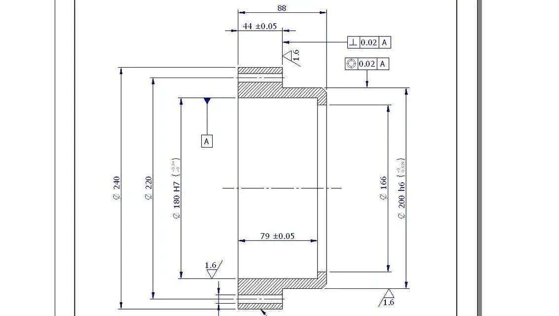
My problem is to assign references for geometric tolerances, as long as the references are of the external surfaces of the components no problem, the problem arises when I want to assign the reference e.g. to the axis of a cylindrical flow, the system seems to fail to "attach" the measuring line and place it a little randomly, as in the attached image.
I am interested in getting the correct formatting of the reference, only that in the guide is not reported much about it.
What's wrong?
Thank you very much.
 

Attachments

  • Quota.webp
    Quota.webp
    27.2 KB · Views: 6
It seems to me that references and geometric tolerances should be placed on the reference lines, not on the quota lines. the edges, in sight or hidden.
that then the system does not feel the axis I do not remember exactly, I should check but this morning windows does not want to start. and anyway: how would then who does the test of acceptance of the piece refer to a theoretical axis that does not exist physically? These tolerances, in the case of holes or trees, must always be referred to a cylinder generator, not to its axis. Of course it is good for this purpose also the reference line of the quota that of the generating one represents the ideal extension.

Bye.
 
It seems to me that references and geometric tolerances should be placed on the reference lines, not on the quota lines. the edges, in sight or hidden.
really the legislation previews the possibility to use axes or plans of symmetry as references, provided in fact to indicate the reference in correspondence of the line of quota of the axis, tree or groove.
that then the system does not feel the axis I do not remember exactly, I should check but this morning windows does not want to start. and anyway: how would then who does the test of acceptance of the piece refer to a theoretical axis that does not exist physically? These tolerances, in the case of holes or trees, must always be referred to a cylinder generator, not to its axis. Of course it is good for this purpose also the reference line of the quota that of the generating one represents the ideal extension.

Bye.
for some tolerances certainly, but for the axes taken as references I have always been told that the way to operate is this, and the text that I use as reference for the industrial technical drawing agrees.
for control I do not know the ways to proceed well, but at the course in which these tolerances were explained we were talking about self-centering spindles for axes or feedback blocks for symmetry plans.
thanks for your intervention
 
I did a test, and it works to me, even if the method you indicate I would not use it since then it would make it very difficult to test the piece (see fig. "tolerances_2". I usually as I told you I prefer to work on real edges (see fig. "tolerances").
 

Attachments

  • tolleranze.webp
    tolleranze.webp
    24.9 KB · Views: 20
  • tolleranze_2.webp
    tolleranze_2.webp
    23 KB · Views: 17
really the correct way to indicate the axis is to connect the reference to the quota line as you can see in this skf catalog table: table tolerances gdtMy problem is that I can't get the right formalism with solidedge.
 
really the correct way to indicate the axis is to connect the reference to the quota line as you can see in this skf catalog table: table tolerances gdtMy problem is that I can't get the right formalism with solidedge.
I use st and not v17, but opening old drawings made with v17, the symbol
I have corrected both on boards and quotas.

I doubt that you have not enabled the check on the reference command
 

Attachments

  • imm.webp
    imm.webp
    5.3 KB · Views: 3
I use st and not v17, but opening old drawings made with v17, the symbol
I have corrected both on boards and quotas.

I doubt that you have not enabled the check on the reference command
I checked, with all possible combinations, and I can't place the reference.
 
@caccia: is the reference on the phi180 quota correct? It doesn't seem to me! ;)

Anyway I have always used these methods and I have never had any problems.
Maybe you have to reinstall se17.
Hi.
 
@caccia: is the reference on the phi180 quota correct? It doesn't seem to me! ;)
I think not, in fact the second image represents the "things not to do", in my opinion, benign!
I just needed to check whether or not he could do some things.
 
ok, so it seems that there are no particular options and/or formatting you have to activate to get the correct formatting of the reference. patience, it will mean that I will use the notations as they are.
Thank you very much to all for availability
 

Forum statistics

Threads
44,997
Messages
339,767
Members
4
Latest member
ibt

Members online

No members online now.
Back
Top