• This forum is the machine-generated translation of www.cad3d.it/forum1 - the Italian design community. Several terms are not translated correctly.

schizzi e snap

  • Thread starter Thread starter Emergent
  • Start date Start date

Emergent

Guest
Hello.
are new in the forum and recently use solidworks.
I come from solid edge, with which I still have no great experience.
I have a problem with snaps that didn't show up in solid edge.
Let me give you an example.
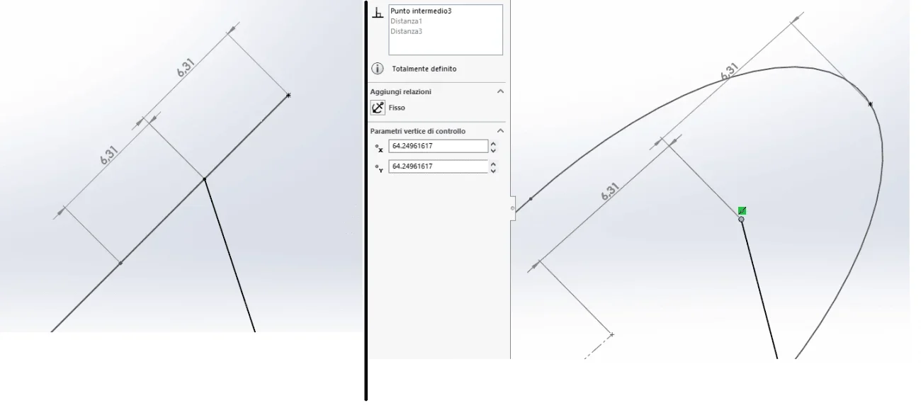
I have to make a loft and I have two sketches on two floors parallel to each other and I want to connect them by drawing a guideline on a perpendicular plane to the two previous ones.
when I go sketching (e.g. with a spline) the software does not "free" the sketches on the two parallel planes.
I hope you understand.
on the right floor I want to draw the spline that connects with the two arches of circumference.
with solid edge, using paritetic elements, the software feels everything, always and anyway.
with solidworks I don't know how to do it.
 

Attachments

  • 1.webp
    1.webp
    35.6 KB · Views: 11
I am confused, the two floors are not parallel but coincident. ..however does not affect the problem.
the spline that will act as a curve guide the collego with the perforated relationship.
I can also draw it with the extremes almost coincident with the arches and then create the relationship, but so the spline is modified (although lightly).
I would like to be able to have more control and with snaps to immediately hear the intermediate point of the bows.
 
Where are the two sketches parallel?
the snap takes it if the right plan intersects the sketch, otherwise it does not know how to interpret the entities.
However it is sufficient to select, holding ctrl pressed, the two points to be connected to have the choice of the applicable constraints.
in such problems it is recommended to attach the file
 
the right floor, on which I want to draw the spline, intersect the two sketches that I want to use for the loft.
I just tried to do the same thing with solid edge and without even enabling paritetic elements the software feels everything, all elements of all sketches.
I also looked between settings and all relationships/snap are enabled.
 
ok...I have wrong term to define the relationship between plans, but this does not affect my question.
thanks anyway for correction.
said this...how do you do in solidworks to make sure that all points of sketches are "feel"?
 
Where are the two sketches parallel?
the snap takes it if the right plan intersects the sketch, otherwise it does not know how to interpret the entities.
However it is sufficient to select, holding ctrl pressed, the two points to be connected to have the choice of the applicable constraints.
in such problems it is recommended to attach the file
as written in the message just above, I can select the points I need and assign a relationship, but I would like to have more control in the design stage, because otherwise the spline is modified, even if very slightly.
 
Okay.
then, now that I am on the pc I see that you did not insert the version in the messages and even in the profile (please do so).
I asked you to attach the file, attach it.
the spline that will act as a curve guide the collego with the perforated relationship.
this allows to assume that the sketch of the guideline is not coincident with the line of the profile sketch (memory wash)
to select the middle point of the arches the right plane must pass through the average axis of the two sketches.
 
"the right floor passes through the average axis of the two sketches "
But maybe I don't know what you mean.
 
after seeing the file, any idea about how to make sure that all the elements of the two sketches can be selectable?
 
I can't see the file because I have 2019 and why now I'm home.
However if the snap does not work select the points manually
 
Okay.
for the moment I am enjoying more solidworks than solid edge, but this thing about the snaps on solidworks is really a disappointment.
Maybe it's solved. ..write here if I find a solution.
 
I'll do some tests tomorrow.
add a few images to better understand the layout of the floors because that arch in addition to the middle point should return the dial snap, of course if the right plane passes through the half-mills as I said.
to tell it all that mainly should return is the coincidence
 
doing some qurello evidence you want to get is not possible with the average point.
and in its way it is also logical because you have to put yourself in the condition of the software.
in fact the projection of the arc on the right is not the arc, but a line whose average point is different from the dial. I'll get you a picture.
to force the selection of the average point however you have to select the type of snap from the toolbar quick clicks
 

Attachments

  • Immagine.webp
    Immagine.webp
    18.7 KB · Views: 3
thanks for the dedicated time.
would quick snap?
I don't understand what it takes, since all snaps are enabled.
Could you explain their use better and when they come in handy?
 

Forum statistics

Threads
44,997
Messages
339,767
Members
4
Latest member
ibt

Members online

No members online now.
Back
Top