oro987
Guest
Good morning to all of you,
my company decided to make tread models for tires with catia v5 migrating to this soft. (i.e. everything and immediately):
in the meantime I read various threads of this forum and thanks also to you I approached the new soft. with less fear and I must say I have acquired some knowledge that I had not before, but I come to the therefore!:wink:
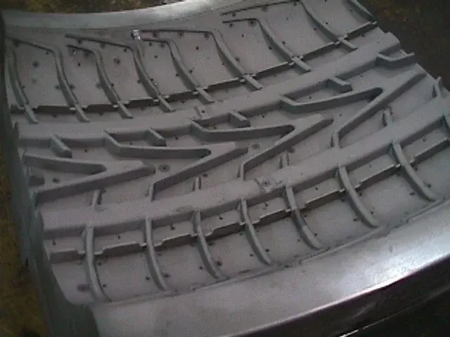
I have to "expalm" a 2d-level writing (pirelli type) inside a toroid and then of course I will have to work it on milling machine.
I remain waiting for some advice and thank you for the attention.
my company decided to make tread models for tires with catia v5 migrating to this soft. (i.e. everything and immediately):
in the meantime I read various threads of this forum and thanks also to you I approached the new soft. with less fear and I must say I have acquired some knowledge that I had not before, but I come to the therefore!:wink:
I have to "expalm" a 2d-level writing (pirelli type) inside a toroid and then of course I will have to work it on milling machine.
I remain waiting for some advice and thank you for the attention.