• This forum is the machine-generated translation of www.cad3d.it/forum1 - the Italian design community. Several terms are not translated correctly.

sheet metal and cyroclar holes

  • Thread starter Thread starter andreaf93
  • Start date Start date

andreaf93

Guest
Good afternoon to all,
is my first post and thank you in advance for the help you can give me, currently I use sw 2016 and my level in design with sw is at first arms.
I designed a sheet metal with the sketch function, then I turned it into sheet metal with the function "basic flange tongue" giving the height I need and the required thickness.
I subsequently created holes with the "guided creation of holes".
Once I make the flat repetition and I measure the diameter of the holes rightly I see that the holes are no longer perfectly circular but oval in the side in which the displacement is carried out and so everything ok.

this flat repetition was also designed by another designer with the same odds and I value that his holes in the flat repetition are more oval than mine, moreover his are pentagons with more angles and sides than mine. (saying it in pentagons: in the flat repetition its oval holes are more circular pentagons while my are more hexagonal oval holes).

If I didn't explain well, please let me know.

of course specific that in the view 3d or in the planting the radius of the dizzying the thickness and diameter of the holes correspond.

Thank you.

Good evening
 
and what exactly would your question be?
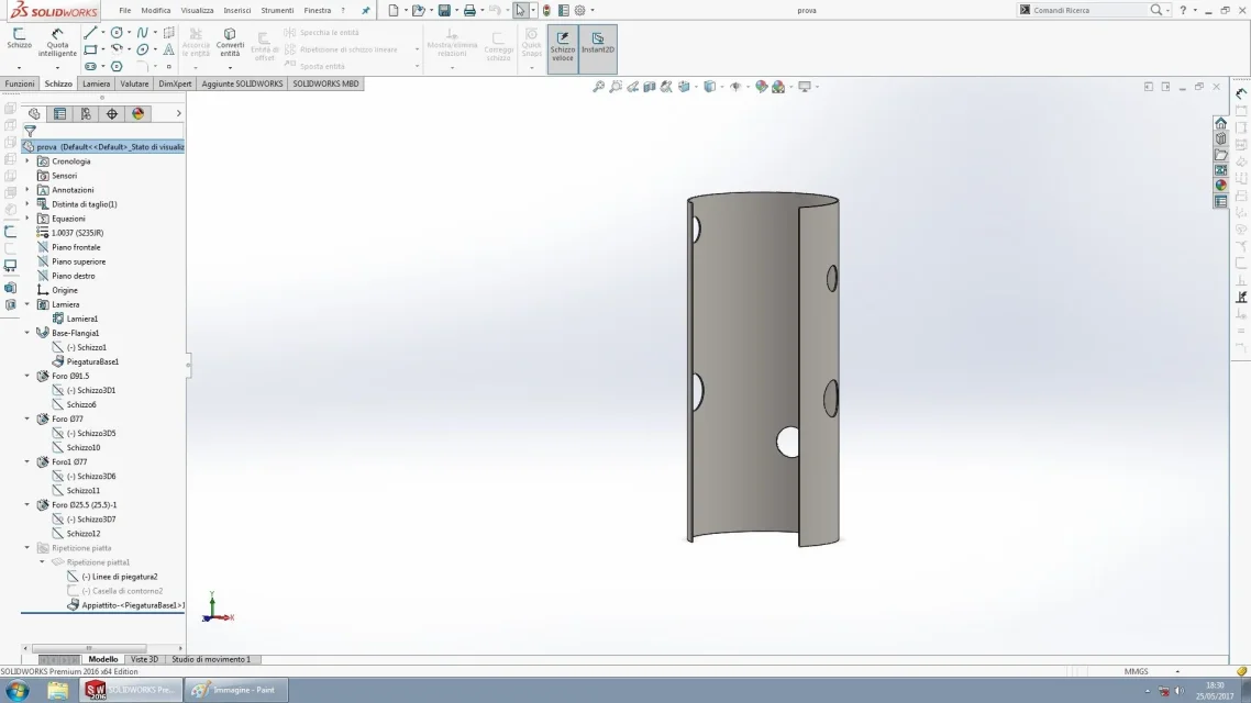
see image of the feature manager to understand the sequence of functions. change sequence or method from different results. You cannot invent the part to analyze its problems by building only a short description.
this leads to imperative suguente: always attach the file to be able to speak the language of the same file. save privacy issues obviously
 
I forgot, the rhombopentaesagonal holes is almost certainly a question of quality of the image to be set in the options of the document

put the software version in the profile
 
I forgot, the rhombopentaesagonal holes is almost certainly a question of quality of the image to be set in the options of the document

put the software version in the profile
Immagine.webpThat's what's required.
the problem is the different portion of the holes in the flat repetition my drop of 7 tenths compared to the historical flat repetition of the company for which I work.

Thank you.
 
at the first glance I saw all the sketches of the underdefined holes and already this is a serious mistake. if you have two uguai holes (ø77) why do two functions?
do the tutorials?
I asked you to attach the file, and I don't think a sheet like that has any industrial secrets. I can't open the file, but latri si and can intervene with construct.
a fundamental question that I forgot to ask is: are the holes made of folded sheet or spreadsheet?
What does that mean? shorten the entirex or narrows the diameter of the hole?
 
at the first glance I saw all the sketches of the underdefined holes and already this is a serious mistake. if you have two uguai holes (ø77) why do two functions?
do the tutorials?
I asked you to attach the file, and I don't think a sheet like that has any industrial secrets. I can't open the file, but latri si and can intervene with construct.
a fundamental question that I forgot to ask is: are the holes made of folded sheet or spreadsheet?
What does that mean? shorten the entirex or narrows the diameter of the hole?
Here's the file.

What do you mean holes sketches are defined?

the holes I made them directly in the solid. I mean that the hole is narrowed so the diameter.
 

Attachments

when the sketch has a less in front it says it is underdefinite. in practice is not completely defined with quotas or constraints. That means you can't handle those sketches exactly. Did you do the tutorials?
that you have made holes in the solid is clear. I did not ask you this, but if they are done before or after the displacement, meaning with this in the operational phase in the workshop. because if you can answer this question you know, logistically, even how the solid must be shaped and how to insert the holes; You miss knowing how to use tools.
It is natural that a hole is ovalized if you practice it on a curved surface and then spread this surface. There are no miracles to avoid it, it is simple physics.
 
when the sketch has a less in front it says it is underdefinite. in practice is not completely defined with quotas or constraints. That means you can't handle those sketches exactly. Did you do the tutorials?
that you have made holes in the solid is clear. I did not ask you this, but if they are done before or after the displacement, meaning with this in the operational phase in the workshop. because if you can answer this question you know, logistically, even how the solid must be shaped and how to insert the holes; You miss knowing how to use tools.
It is natural that a hole is ovalized if you practice it on a curved surface and then spread this surface. There are no miracles to avoid it, it is simple physics.
I don't know what tutorials you mean.
However first it is laser cut the particular therefore also with the holes in question and then it is calandrated.
 
within the program there are tutorials that teach you to use solidworks and to understand the logic of modeling. do at least the basic ones because you are shaping badly and you see the lack of parametric logic

if in reality the holes are made before the displacement you can not in the model rolled out sheets. You need to roll them out.
to do this there are at least two ways to choose from:
- draw the sheet metal, stretch it, make the holes and fold it
- draw the spreadsheet, make the holes, fold it
 
within the program there are tutorials that teach you to use solidworks and to understand the logic of modeling. do at least the basic ones because you are shaping badly and you see the lack of parametric logic

if in reality the holes are made before the displacement you can not in the model rolled out sheets. You need to roll them out.
to do this there are at least two ways to choose from:
- draw the sheet metal, stretch it, make the holes and fold it
- draw the spreadsheet, make the holes, fold it
Meanwhile, thanks for the help you're giving me.
I think it is much more difficult to draw holes on the sheet spread especially with sheet metal. In any case now I try, the holes should always be rounded or should I calculate how much they should be oval when drawing them on the spreadsheet? Thank you.
 
I think it is much more difficult to draw holes on the sheet spread especially with sheet metal
what would be the difficulty in making holes on the spreadsheet?
should the holes always be rounded or should I calculate how much oval should be when drawing them on the spreadsheet?
How are the holes made in the laser workshop? Do you mean ovals?
 
what would be the difficulty in making holes on the spreadsheet?

How are the holes made in the laser workshop? Do you mean ovals?
calculate the precise point in which to make the holes for example the side holes with the view 3d I can center them better i.e. just start from the center of the circle, while in the flat view I do not have a reference point.

to the laser the holes will be made oval in such a way that when the sheet will be rolled out round.
 
calculate the precise point in which to make the holes for example the side holes with view 3d I can center them better i.e. just start from the center of the circle
Too bad I can't open the model because I'm really curious to see what technique you put them in. because something definitely missing since they are not defined completely
If the final result is a round hole then you have to make holes on the sheet metal and the development will give you the geometry of the holes as it will have to be laser cut.
This brings us back to your first question
the problem is the different portion of the holes in the flat repetition my drop of 7 tenths compared to the historical flat repetition of the company for which I work.
Do you have their design? or this difference between your oval and theirs is something to hear?
In the first case if you have the drawings because you embark on inventing and hypothesize measurements, copy that already done and then you study the model and you do all the considerations you need and you should also have the odds for positioning the holes on the expanse.
in the second if they have no data to prove it your result is as good as their
 
Too bad I can't open the model because I'm really curious to see what technique you put them in. because something definitely missing since they are not defined completely
If the final result is a round hole then you have to make holes on the sheet metal and the development will give you the geometry of the holes as it will have to be laser cut.
This brings us back to your first question

Do you have their design? or this difference between your oval and theirs is something to hear?
In the first case if you have the drawings because you embark on inventing and hypothesize measurements, copy that already done and then you study the model and you do all the considerations you need and you should also have the odds for positioning the holes on the expanse.
in the second if they have no data to prove it your result is as good as their
Unfortunately I only have the dxf of the file.
the hole I designed them with "guided creation of the holes" making the 3d positioning allowed by the function itself.
 
If you have the dxf you have the design done and finished. you just need to copy it
the hole I designed them with "guided creation of the holes" making the 3d positioning allowed by the function itself.
creation wizard holes ok. but if a sketch is underdefinite it means that it has degrees of freedom. in that sketch you only have one point, which means that that point some movement must have it: vertically, on the curve of the perimeter or who knows what else.
can you attach idxf by cleaning it from all sensitive information?
 
If you have the dxf you have the design done and finished. you just need to copy it

creation wizard holes ok. but if a sketch is underdefinite it means that it has degrees of freedom. in that sketch you only have one point, which means that that point some movement must have it: vertically, on the curve of the perimeter or who knows what else.
can you attach idxf by cleaning it from all sensitive information?
of the historical file I only have the dxf to go to cut but I do not have the 3d.

Let's say that the points where I ran the holes I made them with a 3d sketch using construction lines.
 

Attachments

You could also add some information about your files. . .
in the last attachment there are two dxfs. I used the one with correct writing, the other what is it? If you put it to something it needs to be, but to what?
if you also added a plan of the sheet metal I should not have guessed radius of fold and sheet thickness (I can not open your model)... but apart from this with the above measures approximate the holes made on the grille and then spread almost like those of the dxf
If you turn me the dwg or dxf of the sheet metal plant tomorrow I see to correct the model and then I attach it.
If I'm putting anyone in 2016 from a look at your model well come
 
You could also add some information about your files. . .
in the last attachment there are two dxfs. I used the one with correct writing, the other what is it? If you put it to something it needs to be, but to what?
if you also added a plan of the sheet metal I should not have guessed radius of fold and sheet thickness (I can not open your model)... but apart from this with the above measures approximate the holes made on the grille and then spread almost like those of the dxf
If you turn me the dwg or dxf of the sheet metal plant tomorrow I see to correct the model and then I attach it.
If I'm putting anyone in 2016 from a look at your model well come
the file: dxfcorretto is the historical one of the processing with which we always produced the particular.
the file: dxfmio is the one from my design.

I also attach pdf of the dwg. (I can't send you the real dwg because I'm not home, you should still find all the information you need, let me know).

thanks and good day.
 

Attachments

I forgot: consider only 77 holes, because the others had to draw them with a different diameter than the original for internal production changes.

what I do not understand is because having the same radiation, the same thickness and same diameter of holes in development phase change the quotas ie: in the historical dxf "dxfcorretto" the hole size 78.12 while in my dxf "dxfmio" the hole size 77.40.
 
the historical dxf was obtained as? from a 3d program? if yes, always solidworks?
your 77.4 I only get it by putting as a factor k=1. decreasing factor k the measure shrinks. this therefore is an important data
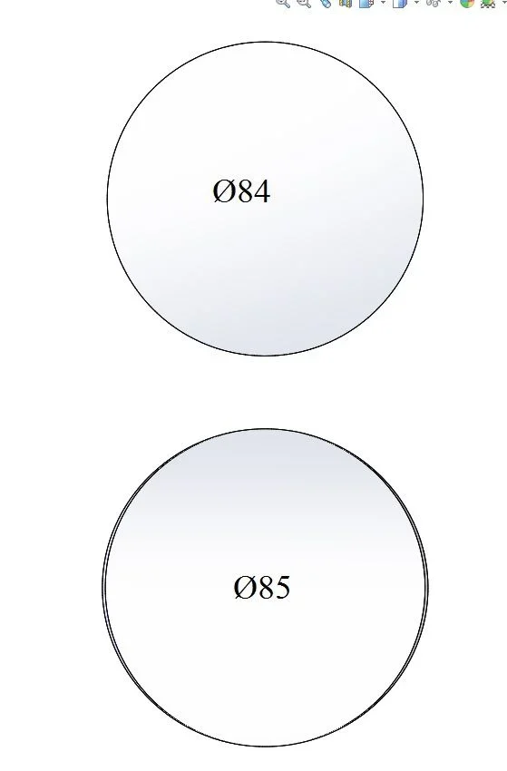
rather there is a strange thing that happens: up to a diameter of ø84 the flattened hole has the net edges, while with ø85 you can see the shrinkage due to the bending effect. strange behavior that could have some relevance with the difference of measures found if different software were used, between the historian and the current, for the management of the sheets.
in the image you see the flattened sheet. I approached the holes to show the difference. with further verification I have noticed that the modification of the cut already has between the diameter ø84.1 and ø84.2Immagine.webp
 

Forum statistics

Threads
44,997
Messages
339,767
Members
4
Latest member
ibt

Members online

No members online now.
Back
Top