• This forum is the machine-generated translation of www.cad3d.it/forum1 - the Italian design community. Several terms are not translated correctly.

solidworks 2011: richiesta informazioni

  • Thread starter Thread starter PiegatoreSolidworks
  • Start date Start date
I have a nvidia gtx 275 with 1 gb of ram and with updated official nvidia drivers so on certification I don't think I have problems even if in that menu you linked there are only picture cards and my no (which cmq is very well known).


But I think I've already activated it or not? ?
I wrote:
"the realistic effect called realview is a prerogative of the cards called 'certified'. "
And then I told you to look here.But apparently you didn't.
If it's not there, it means you don't have realview.
If you want it anyway, there's the solution on the forum....and let's see if you find it.
 
I wrote:
"the realistic effect called realview is a prerogative of the cards called 'certified'. "
And then I told you to look here.But apparently you didn't.
If it's not there, it means you don't have realview.
If you want it anyway, there's the solution on the forum....and let's see if you find it.
I had seen the menu that you linked me but as ste tabs I have never seen them felt (perhaps because I do not know very closely the world of 3d editing) and since my nvidia is not the last of the video cards, indeed, I imagined it was more a speech of hw power and not a matter exclusively of brand....what it obviously is.

If you want it anyway, there's the solution on the forum....and let's see if you find it.
http://www.cad3d.it/forum1/showthread.php?t=23270&highlight=realviewThanks for reporting, it works perfectly. ;)
 
I had seen the menu that you linked me but as ste tabs I have never seen them felt (perhaps because I do not know very closely the world of 3d editing) and since my nvidia is not the last of the video cards, indeed, I imagined it was more a speech of hw power and not a matter exclusively of brand....what it obviously is.


http://www.cad3d.it/forum1/showthread.php?t=23270&highlight=realviewThanks for reporting, it works perfectly. ;)
realview is supported ("officially") only by the framework boards (which is not another brand but always nvidia, dedicated to professional programs such as cad), or by firegl ati.. However it is all explained at the beginning, in the online guide.

but as you have seen there is the way to "add" this limitation to be able to use even the gaming cards.

greetings
Mar
 
as from title, I noticed this bug: if I try to access the tutorials
I get a script error if I change the language using English
works very well, in English of course.
Can you check, please?


Thank you. :wink:
solved with the S2.
 
solved with the S2.
there was a more "do it yourself" method
as soon as you go to tutorials do not click on the lecture menu in the center but above go to exhibition and you will see the list of all tutorials.
problem solved :wink:

rather someone manages the tutorial:use of the matching function to merge multiple bodies? ?
when I try to select the two bodies to match I receive the message:
impossible to select the functions. select a solid body from the function tree or the graphic window.
 
I forgot to write that the lesson section is multicorpo party.
(that balls I am made that after 15 minutes you can no longer tell the message).

mmmm... maybe I understand:
by selection of the graphic area he intended to click on the piece and not on the tree that is always displayed in the graphic area.
 
I forgot to write that the lesson section is multicorpo party.
(that balls I am made that after 15 minutes you can no longer tell the message).
How dare you!
with the effort we have done (in a few) to make sure that there is this "feature" you do not dare to complain or raise dusts otherwise I pass on your hands with the front roller, which is enough and advances: :tongue:
 
Thanks :finger:

I have a new problem:
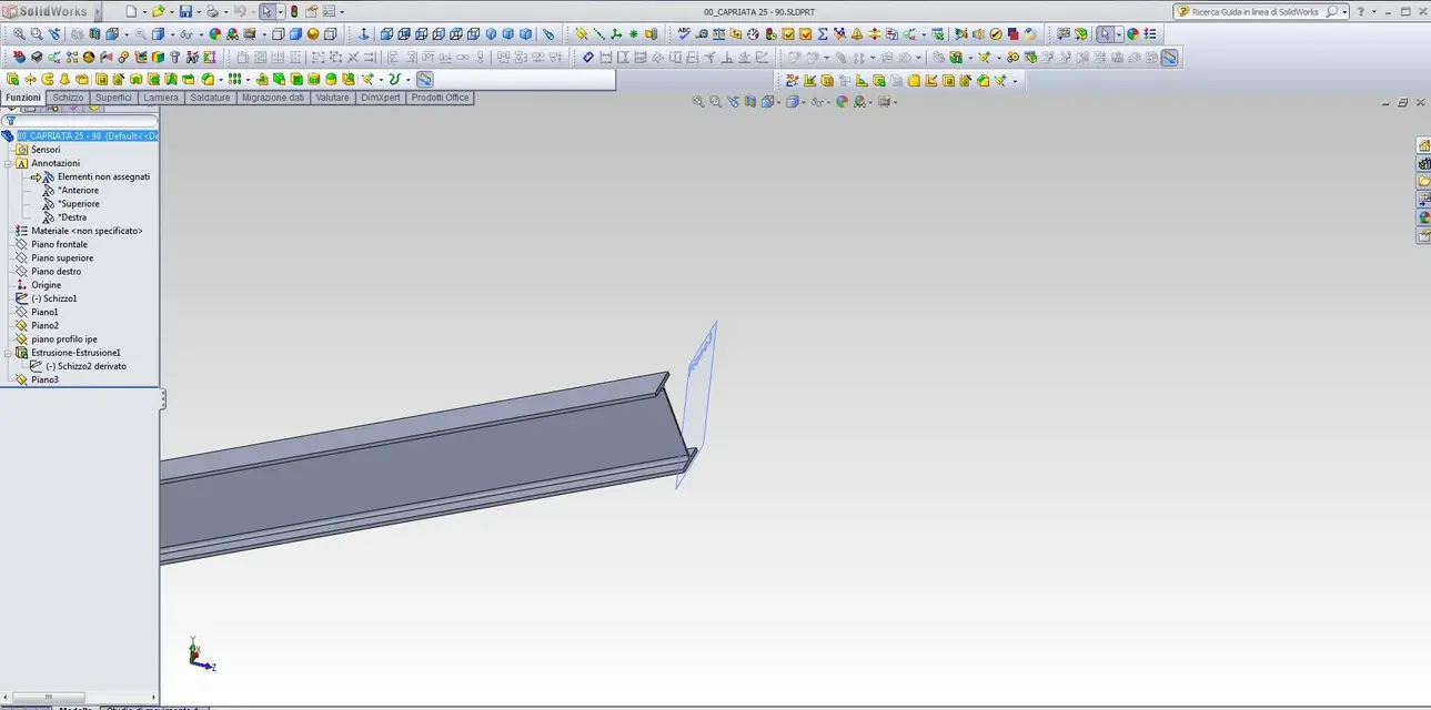
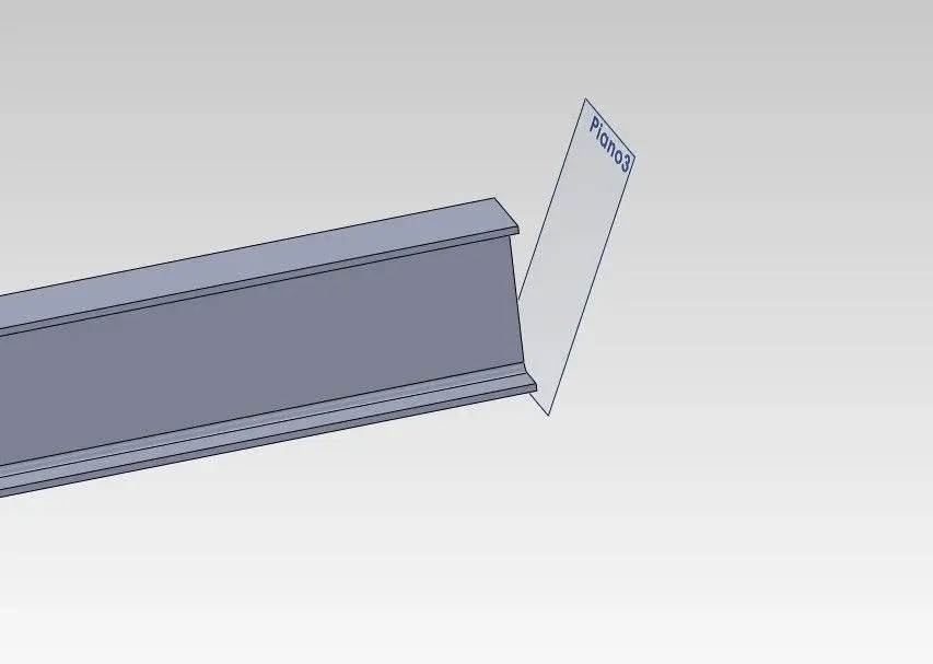
the beam you see in the photo is tilted so, it starts with the perpendicular face on the tilted plane but ends with the tilted face compared to that plane of exactly 25°.

My goal is to get the profile on the right tilted plane (which is then tilted to the beam but is perpendicular to the ground).

Now, I was thinking about some extrusion function that, specifying the double t section of the beam and the combing plan, extends the final stretch right up and beyond the plan created to the right of the design.

last night I tried with some extrusion tools but without succeeding.
If you really want to tell me the process, could you tell me a link or tool for the egg?

Thank you.
 

Attachments

  • 1.webp
    1.webp
    13.9 KB · Views: 7
  • 2.webp
    2.webp
    11.5 KB · Views: 7
  • 3.webp
    3.webp
    94.4 KB · Views: 9
My goal is to get the profile on the right tilted plane (which is then tilted to the beam but is perpendicular to the ground).
in the extrusion function, where you define the final conditions, choose "up to the surface" then select the tilted plane. done.

If you really want to imaprate to use swx it is intile that you plan without having the abc, that's why it's just the...
Take a subject at a time and unveil it thoroughly.
parts with sketches and try to use all the sketch tools by learning to bind them, quota them etc.
then go to the feature, one at a time.
Have you seen how many options there are in the extrusion function? Well, try them all, several times, and you'll see that then you'll remember which tool you need from time to time to build that specific geometry.
But I swear that from today I won't break your bales with these advice from the past :rolleyes: and I'll let you do as you think:
 
in the extrusion function, where you define the final conditions, choose "up to the surface" then select the tilted plane. done.

If you really want to imaprate to use swx it is intile that you plan without having the abc, that's why it's just the...
Take a subject at a time and unveil it thoroughly.
parts with sketches and try to use all the sketch tools by learning to bind them, quota them etc.
then go to the feature, one at a time.
Have you seen how many options there are in the extrusion function? Well, try them all, several times, and you'll see that then you'll remember which tool you need from time to time to build that specific geometry.
But I swear that from today I won't break your bales with these advice from the past :rolleyes: and I'll let you do as you think:
Thank you.
I will listen to your advice but believe me if I tell you that yesterday (Sunday) I spent all day doing tests (see attached image).
All in all to be the first day "serious" doesn't seem bad, then maybe I'm wrong.

for the question I asked before I also attach the file (sw 2011).

Thank you for your help.
 

Attachments

Thank you.
I will listen to your advice but believe me if I tell you that yesterday (Sunday) I spent all day doing tests (see attached image).
All in all to be the first day "serious" doesn't seem bad, then maybe I'm wrong.

for the question I asked before I also attach the file (sw 2011).

Thank you for your help.
under the conditions in which the file is located right now, the most painless system
is this:


However, you couldn't stretch it further and then cut it with an extruded cut?
if at least hitch you play on Sunday...:biggrin:

I've noticed some walking plans in limbo, are they part of references in the environment together?
 

Attachments

if I can give you advice, learn to use structural members( see welding functions http://help.solidworks.com/2011/ita....html?id=261f5ab5531c4fd18987f2d439fdb4d8#pg0).
you will realize that creating traps and frames, even complex, will be
normal practice.
I put you a couple of files I'm working on (the cusp with the ipe is just an experiment) made with that method so that you can see the potential of the sw.
 

Attachments

However, you couldn't stretch it further and then cut it with an extruded cut?
if at least hitch you play on Sunday...:biggrin:
no Sunday I used it to do everything you see in the image above not to solve this problem:smile:
I've noticed some walking plans in limbo, are they part of references in the environment together?
Yes,
I used them to experiment and adjust.

Thank you very much for the video.
You don't know how important they are to me:finger:
if I can give you advice, learn to use structural members( see welding functions http://help.solidworks.com/2011/ita....html?id=261f5ab5531c4fd18987f2d439fdb4d8#pg0).
you will realize that creating traps and frames, even complex, will be
normal practice.
I put you a couple of files I'm working on (the cusp with the ipe is just an experiment) made with that method so that you can see the potential of the sw.
but I saw this:
you eventually have structures where the modular component is repeated consistently and numerously.
If you notice, the image I posted is more diversified in geometry and components and it seems to me that the welding function is not so decisive (but I can be wrong).
 
....
but I saw this:
you eventually have structures where the modular component is repeated consistently and numerously.
if known, the image I posted is more diversified in geometry and components and It seems to me that the welding function is not so decisive (but I can be wrong).
Mah, I think it's a bit rushing your conclusion: have you waited for the entire loading of the pergola traliccio? have you explored the way to draw in 3d environment, angle cuts, head-to-head cuts, welding thick cuts, inserting fasteners?? ... all in the environment sldprt?
In 2 minutes I don't think you had time to see this.

ps: the joke on the "domenic" was "a joke" :smile:
 
I attach the plant placed by you designed in welded environment.
examines carefully how it was built.
I didn't put foot and dice.
 

Attachments

Mah, I think it's kind of rushing your conclusion.
And you're right.
My statement was a rush.
What I still miss is what advantages it offers the welding mode compared to the classic procedure of composing the individual parts and then reuniting them in a single set.

maybe the presence of tools made ad hoc for profiles and structures like that? ?

ps:
Mike, thank you again for your attention.
 
And you're right.
My statement was a rush.
What I still miss is what advantages it offers the welding mode compared to the classic procedure of composing the individual parts and then reuniting them in a single set.

maybe the presence of tools made ad hoc for profiles and structures like that? ?

ps:
Mike, thank you again for your attention.
We do this: in some time you will tell me what the benefits are
Welding.
I don't want to influence you.
As soon as you start using them, you can't help it, trust me.
:smile:
 
a question.
an ultradefined design is a basic design not correct?
because I often put extra quotas that for me are useful but sw indicates me as odds that ultradefine the design.
But I don't know if I can leave them or they could give me trouble.
 
a question.
an ultradefined design is a basic design not correct?
because I often put extra quotas that for me are useful but sw indicates me as odds that ultradefine the design.
But I don't know if I can leave them or they could give me trouble.
You can't put two odds in charge of the same size, otherwise you can risk big confusion. said that you can still put one that commands and the other guides, so you can view them and keep them under control without ultra-definition.
 

Forum statistics

Threads
44,997
Messages
339,767
Members
4
Latest member
ibt

Members online

No members online now.
Back
Top