• This forum is the machine-generated translation of www.cad3d.it/forum1 - the Italian design community. Several terms are not translated correctly.

solidworks: surface cut

  • Thread starter Thread starter PICO
  • Start date Start date

PICO

Guest
do you know if there is a way to make a superficial cut on selected faces?

I'll explain.

we imagine having a solid, for simplicity a cube or a parallelepiped.

we imagine drawing a plan or a planar surface that intersects it.

Good.

if I make a cut with surface (passing) they generate 2 bodies distinct from the initial solid.

if I wanted to make a cut that penetrates the body only of 1 cm on each face, that is a line that enters every face of the tot solid, but does not cut it into its inner core, is it possible?? ? ? ?
or I would like to have a reticle of subdivisions on the various faces, but maintaining a single body.

would be great if you could select which faces should receive the cut and which should be left intact... .

thanks to the magician who can answer me.
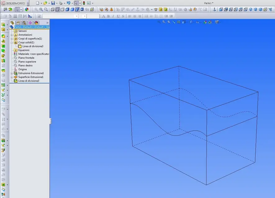
 
do you know if there is a way to make a superficial cut on selected faces?

I'll explain.

we imagine having a solid, for simplicity a cube or a parallelepiped.

we imagine drawing a plan or a planar surface that intersects it.

Good.

if I make a cut with surface (passing) they generate 2 bodies distinct from the initial solid.

if I wanted to make a cut that penetrates the body only of 1 cm on each face, that is a line that enters every face of the tot solid, but does not cut it into its inner core, is it possible?? ? ? ?
or I would like to have a reticle of subdivisions on the various faces, but maintaining a single body.

would be great if you could select which faces should receive the cut and which should be left intact... .

thanks to the magician who can answer me.
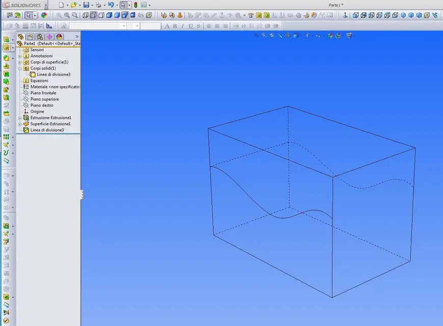
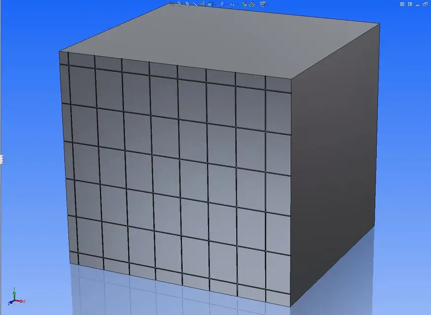
I think you can use the "division line" function.
pictures with all separate faces/only some
ps: I am not a magician, I am a simple sorcerer... :biggrin:
 

Attachments

  • Div.webp
    Div.webp
    69.8 KB · Views: 36
  • Div-par.webp
    Div-par.webp
    70.4 KB · Views: 23
the problem is that I have to make a cut that has a thickness.
design facade coverings in aluminum panels, so I have to have an escape between the panels of determined width.
I should draw a cutting line (with thickness) that intersects various faces of the solid but not the "rompa" in many bodies....
 
we imagine having a solid, for simplicity a cube or a parallelepiped.
we imagine drawing a plan or a planar surface that intersects it.
Good.
if I make a cut with surface (passing) they generate 2 bodies distinct from the initial solid.
if I wanted to make a cut that penetrates the body only of 1 cm on each face, that is a line that enters every face of the tot solid, but does not cut it into its inner core, is it possible?? ? ? ?
or I would like to have a reticle of subdivisions on the various faces, but maintaining a single body.
depends very much on the type of solid, but a road is to make the cuts first, then simply to recreate the "nucleus" by making a new extrusion or the offset from the initial faces, obtained perhaps from reference surfaces at the beginning of thehistory.
or if you have no problem having a multibody part do the nucleus, then create the offset of the nucleus and finally make cuts with the surfaces by selecting only the external body.
or still make the solid and for the cut instead of using a full surface create "bucata" with the shape of the internal profile equal to the offset from the external faces you need.

In short, the streets are so many and the choice didpends by the shape of the solid you have to realize and the freedom of change you want after
 
Is that what you want to get??
(I have a certain experience in sheet coated facades)
 

Attachments

  • Coso così.webp
    Coso così.webp
    53.6 KB · Views: 35
  • Coso così.zip
    Coso così.zip
    233.4 KB · Views: 7
you are right, I have given few explanations going directly to the conclusion.
I'll explain.

the central body is the relief of the building to be covered and can have any shape, even complex or rounded, however it is always stylized and constituted by a single solid body.

the quickest method to do my job is to make the offset of the faces of the building that will be covered and then thickness 35 mm (the thickness of the panels).

In this way I have a second body, unique, which consists of all the external faces of the coating. has an irregular pattern in all dimensions of the space and constant thickness 35 mm.

At this point I have to slice it several times, both in horizontal and vertical, with step not necessarily constant until the final lattice of the panels that make up the coating.

since the panels can be really many I have the problem that the obtained multibody part is too heavy and becomes unmanageable.

the alternative way to make a set of parts has other limits (less practical creation and modification in my case). keep in mind that I can have multiple identical panels repeated several times without an apparent logic of repetition. making a series of cuts on one body is definitely faster and more practical.

the idea of reuniting bodies after the slicing by extrusion on the hidden face honestly I didn't think of it. little refined but can work to lighten the file when it gets too heavy.

It seems strange that you can't make a "superficial" cut on the various faces of a body... it would be the egg of colombo... .

I’m also evaluating the transition to more specific software for architecture, revit type or progeny, but I’m afraid to lose in flexibility.
 
a question: if the building has curved facades, will you still use flat panels?
I think so, I don't think we're going to tear down the panels.
If so the approach is wrong, because you have to discuss the curves in straight elements.
 
panels are often calandrated and follow the curve, depending on how much you want to spend the customer.

in case instead of flat panels and then discreet curve to segments obviously design differently. I start from the building plant, I put to a tot of offset from the curved wall and design in sketch the broken panels that I then extrude. That's not my problem. .
 
panels are often calandrated and follow the curve, depending on how much you want to spend the customer.
in case instead of flat panels and then discreet curve to segments obviously design differently. I start from the building plant, I put to a tot of offset from the curved wall and design in sketch the broken panels that I then extrude. That's not my problem. .
I didn't realize it was face coverings.
Now, I have no idea how many panels you need to handle, but for so many that I subscribe to what is said by maxopus: working on a multibody part or worse a unique body imho is a wrong approach.
you have to make the axieme, maybe built on a reference part that then can really be a single body, or on a sketch of layout that will command the geometry of the panels, position of the profiles etc.
I believe that by exploiting the repetition of components guided by features and other functions of the assemblies you can do without problems.

If you do a single body then I wonder how you handle all the fixing components (profiles, brackets and everything else) to make distinct materials etc. now that I have asked myself the answer: become unmanageable:smile:
 
Mine is a hybrid design.
for a series of reasons the complete project of everything (substructures, mountings, profiles, brackets etc) must be made in 2d autocad.
and works well both as practicality and as speed of execution.

what I require at 3d is only the architectonic general of the building.
This allows me to visualize the particular knots well, to make a detail of the complicated areas, to have the updated sections at every level that can serve me, to present to the customer of the exhaustive images etc.

I have tried several times to use the axieme, but it becomes slender.
repetitions also become a nightmare.
My cut lattice can vary at any time to move a window, for a customer preference, for a difficulty of realization in the workshop... .
I have no regular repetitions and can happen to have to delete a row of panels without having to overturn all the remaining. at this stage the parameterity can become your worst enemy. for these things in fact autocad is unbeatable. Iron what you feel without fear that you move everything else.

In practice I have to marry the convenience of visualization, choice of areas, portioning of sw plans etc with the banality of autocad modification in the second part of the design.
 
Mine is a hybrid design.
for a series of reasons the complete project of everything (substructures, mountings, profiles, brackets etc) must be made in 2d autocad.
and works well both as practicality and as speed of execution.
what I require at 3d is only the architectonic general of the building.
I don't understand your workflow, but "your will is done"...
Of course, I don't get on the cross with my method of doing everything in 3d:tongue:
 
to draw all the details in 3d I would put the triple of the time without receiving advantages, also because at the end of the whole design cycle I have to pull out the executive boards of every single element (centinaia) to pass them to the workshop.
in this autocad is unbeatable.
in its simplicity, with various copies and pastes, blocks.... etc. is a flash.
 
because of the hundreds of harvests on the table the 3d brings you advantages.
you have all the views you want automatically, if you add changes to the particular you do not have to review n views and sections, you have weights, distinct cutting and other information without needing to do calculations manually.
time is an investment. . .
 
because of the hundreds of harvests on the table the 3d brings you advantages.
you have all the views you want automatically, if you add changes to the particular you do not have to review n views and sections, you have weights, distinct cutting and other information without needing to do calculations manually.
time is an investment. . .
I fully agree.:finger:
with model 3d I can create all the views and sections that I want in two clicks of the mouse, I don't have to put in place anything because they are associative, I don't have to check hidden lines and lines in sight, because if the model is right, the views are right, I have other information like weight and distinct base without having to do anything... the time you lose to create all the views in 2d (more than non associative), you have already recovered it once you finished the 3d model, just because to titar out all the 2d executive boards he thinks about it automatically, and it is a matter of a few seconds.:smile:
 
to draw all the details in 3d I would put the triple of the time without receiving advantages, also because at the end of the whole design cycle I have to pull out the executive boards of every single element (centinaia) to pass them to the workshop.
in this autocad is unbeatable.
in its simplicity, with various copies and pastes, blocks.... etc. is a flash.
I don't want to talk to you, but at this point I think you didn't fully understand how to do it and what it means to design with a 3d cad (parametric or not) whose 2d boards are always associated with the 3d model.
to think of passing in the workshop the drawings and the constructive details of hundreds of details obtained every time in manina from a two-dimensional autocad makes me come the hive to the only thought of the time that you have to dedicate to check not having made chaplained. . .

I add that if you have to use swx to make a maximum 3d with the appearance of the panels to show something to the customer (like a parallelepiped with tot panels simulated by the grid of cuts) you are firing at the flies with the cannon.
 
I understand your perplexity but I assure you that I know what I do.
I am open to every kind of improvement but in my case unfortunately 3d does not help.
(as I wish it wasn't true).

I know well both autocad and solidworks (that I use for 12 years) and unfortunately I do not see any other solutions. in these days also came the company of the technicians of the progeny, of revit and of inventor (as well as of alma for the cam). all, like you, looked at me as crazy for my design method, but after a deepening of the production needs they surrendered to admit the limits of their products for my work.

3d is not used in a reductive way.
Obviously if I have to make a single flat wall or a trivial parallelepiped does not make sense to use it and do everything in autocad.
but very thick I find myself with destroyed buildings and crazy shapes, with panels intersecting with skewers and non perpendicular planes (or curves).
when the building is complex, drawing it in 2d leaves you hidden parts, areas to be "imagined", curved parts or projected skewers that can deceive, sections are difficult and long to draw, the undefined knots.
instead having it in 3d puts you safe and makes you start from a certain base, with the convenience of all the views ready and updated at all times.
even just having the individual prospects on each side of the building all beautifully divided and with executive measures is a good gain that justifies its use.

On the other hand, finishing the design with 3d is immant (not to say impossible).
the individual panels have a myriad of details that would be infinite to draw (smused bags where the frieze, grooves, holes for rivets, thorns, squares, sunshades, subsquadri, notes on the painting verse. ...).
all the folds of the panel, which I now stylize with a vertical section detail and a horizontal and cup neck in a moment, I should apply them to every single part of the axieme.
I should lose hours to finish the model of every single panel when I have hundreds.
Not to mention the scarcity of the table and the quotation of solidworks, which I think is very lacking.
and without talking about the substructures and the thousands of plates, mountings, brackets that complete the overall picture.
 
all the folds of the panel, which I now stylize with a vertical section detail and a horizontal and cup neck in a moment, I should apply them to every single part of the axieme.
I should lose hours to finish the model of every single panel when I have hundreds.
only for clarification: It's not like that at all.
in fact it is enough that you create a smart part with different variations inside (with sunshades, grooves and beautiful company) and when you go to put it on the table, select only the one that interests you within the same single file and the game is done; a few seconds and you have already created the beautiful table that ready.
Basically, you do it once it's worth all.
Not to mention the scarcity of the table and the quotation of solidworks, which I think is very lacking.
and without talking about the substructures and the thousands of plates, mountings, brackets that complete the overall picture.
I have to correct you here too: It is enough that you share the model well (i.e. the odds you put them in the various sketches that determine the part) and with a simple click the calls in the table.

therefore you do not have to requote a good thing because you have already done it in the model and you do not have to remake the table for all the details as you just copy and change the name to the table of the first piece, with all its annotations and various quotas, and simply go to replace the model with the different variations of the various types of your pieces present in the respective files.

As you see, these things you said, are all perfectly feasible in 3d with a considerable time saving and to the full advantage of precision and fidelity of representation. I don't think so much.
then it is clear that you have to build models made well, but once you do this go that is a beauty!:smile:
 
I appreciate your enthusiasm, but as I told you, even the vendors of its software have surrendered, there are various aspects that prevent you from gaining time... .
the speech is articulated.
You should come visit me in the company to realize it.... :
 

Forum statistics

Threads
44,997
Messages
339,767
Members
4
Latest member
ibt

Members online

No members online now.
Back
Top