
• This forum is the machine-generated translation of www.cad3d.it/forum1 - the Italian design community. Several terms are not translated correctly.

structure creation (in assembly) with my profiles

  • Thread starter Thread starter 19marco77
  • Start date Start date
I tried that command, too. but what I ask is if the measure (for example) of the 2 short vertical profiles is determinable externally to the guide sketch or if I already have to calculate the 2 measures to get to the center of the 2 profiles above and below?
the profile follows the sketch then, with edge treatment you can manage what type of union you want between the profiles example if you want them at 45° angle or insert a closure...(I don't know if I understand what you mean )
 
cabbage, are you right I have 2012 but would you like to get what is in the image?
Don't worry. No problem. I can get the picture as I need. in my doubt it is only about the "difference" that there is between the length of the guide sketch and the resulting in extruded profile.
to say. I need measures as an attachment.
by putting the measures I need as it has placed eboss extrusions I am not with the final measures.

are random measures. but I hope to understand my doubts
 
Don't worry. No problem. I can get the picture as I need. in my doubt it is only about the "difference" that there is between the length of the guide sketch and the resulting in extruded profile.
to say. I need measures as an attachment.
by putting the measures I need as it has placed eboss extrusions I am not with the final measures.

are random measures. but I hope to understand my doubts
Look at my file I posted later and let me know if that's what you meant... if this is how the command identifies the profile:/
 
control and modification of the measurements of such a frame can occur through a layout sketch in an appropriate plane (to control the width for example on the right plane, to control the depth of the left plane etc... etc...).
by appointing the sketch in the tree, for example " font tracing" you can change the size of the object simply by editing that sketch.
logical that the sketches that will be used for extrusion of the structural elements will have to be correctly correlated usant coincidence relationships and what else.
If I'm in good tonight I'll post a tutor.:rolleyes:
 
Don't worry. No problem. I can get the picture as I need. in my doubt it is only about the "difference" that there is between the length of the guide sketch and the resulting in extruded profile.
to say. I need measures as an attachment.
by putting the measures I need as it has placed eboss extrusions I am not with the final measures.

are random measures. but I hope to understand my doubts
But then the problem is that you want the tube to be in the way of the sketch, so the problem is that the tube has the axis that coincides with the frame sketch?
 
control and modification of the measurements of such a frame can occur through a layout sketch in an appropriate plane (to control the width for example on the right plane, to control the depth of the left plane etc... etc...).
by appointing the sketch in the tree, for example " font tracing" you can change the size of the object simply by editing that sketch.
logical that the sketches that will be used for extrusion of the structural elements will have to be correctly correlated usant coincidence relationships and what else.
If I'm in good tonight I'll post a tutor.:rolleyes:
Here. Maybe with what you just wrote, you hit the problem :biggrin:

But... how would someone say... a tutor would be good and right :p (naturally when you have time to do so).
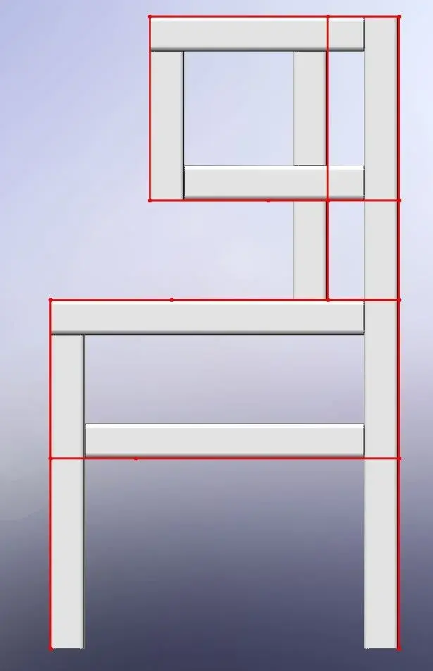
 
Don't worry. No problem. I can get the picture as I need. in my doubt it is only about the "difference" between the length of the guide sketch and the resulting in extruded profile.to say. I need measures as an attachment.
by putting the measures I need as it has placed eboss extrusions I am not with the final measures.

are random measures. but I hope to understand my doubts
. is given by the profile measurement you go to extrude, from your image you see that you have destroyed all the profiles leaving the hook to the center.
for horizontal sections (one at a time using "new group") you could have clicked on "identifying profile" and change the hook, then you could shorten the vertical tube that would be carried out by the horizontal one, in fact.
easier to say than to do.
 
Here. Maybe with what you just wrote, you hit the problem :biggrin:

But... how would someone say... a tutor would be good and right :p (naturally when you have time to do so).
do you want to get this result then?
 

Attachments

  • Cattura.webp
    Cattura.webp
    9.1 KB · Views: 6
But then the problem is that you want the tube to be in the way of the sketch, so the problem is that the tube has the axis that coincides with the frame sketch?
The problem is that I don't know how to handle this difference highlighted in figure. Do I have to always calculate the odds to get to the sketch or is there any other way?
For example. I need a 500 profile. but the extrusion turns out to me 430. If I move the reference marker to find just 500 then maybe another profile of the frame goes me out of quota.

if there was a way to say:
I do a random sketch and then to extrusion made imposed distances and measures.... That would be convenient. and I don't think only for me.

the good mike offered to prepare a tutor.. If I'm not really snooze then I should understand how to handle everything!! :rolleyes:
 
do you want to get this result then?
Unfortunately not:( if you look at your image, the horizontal profile at the top is shorter than the guide sketch.

If I want that 500 mm profile I have to do a longer sketch.
 
Unfortunately not:( if you look at your image, the horizontal profile at the top is shorter than the guide sketch.

If I want that 500 mm profile I have to do a longer sketch.
you now think I have understood what you want to get, there are two ways or mind create the structural element to set in the interest group the suitable edge treatment or perform subsequently shorten extend to adapt the angle to your needs.
 
Unfortunately not:( if you look at your image, the horizontal profile at the top is shorter than the guide sketch.

If I want that 500 mm profile I have to do a longer sketch.
You are not obliged to draw everything in 3d you know... You can also have 2ds where you're comfortable:biggrin:
 
I've already done it many posts ago, but maybe you didn't understand it and I rewrote it:... then I am writing all the same things in different posts and written differently. . . I don't understand anything anymore. :biggrin:
Think of me... ahahahah.. I must resign myself to having to take into account the thicknesses to be added to the sketch to get the profile of the right length.. .

I'm working on it anyway;) thank you all.
 
Thanks eboss.. everything is reduced to start well with the first profile identifiers otherwise then you fall in and you have to change them all if you do not find a possible alignment. . we hope you never understand me.. :p
if you can do it using the structural member's options, alternatively use the command "extended combination":biggrin:
 

Forum statistics

Threads
44,997
Messages
339,767
Members
4
Latest member
ibt

Members online

No members online now.
Back
Top