• This forum is the machine-generated translation of www.cad3d.it/forum1 - the Italian design community. Several terms are not translated correctly.

study movement cart

  • Thread starter Thread starter andrea1901
  • Start date Start date

andrea1901

Guest
Bye to all,
I am planning with solidworks 2011 a pair of handcrafted trolleys to lift the bike and be able to park it comfortably in the garage.
Now that now practically finished the model I would like to check if, applying a certain weight on the pedane the cart behaves as I wish, so that it gives enough size and thickness of the materials and especially as study of the movement of the lifter in relation to the cart.
I tried to follow the tutorials attached to solidworks but don't treat my exact case and so I'm a bit in trouble given my inexperience.
Can any of you guru help me?

thanks for the attention
Andrea
 

Attachments

  • Carrello posteriore.webp
    Carrello posteriore.webp
    11.6 KB · Views: 78
It's not difficult.

1) active solidworks simulation
2) new static study
3) insert the constraints (set to 4 wheels)
4) insert force on the supports
5) click on run and calculate mesh and tensions

Obviously, the mechanism must be put in a stable position and then load the force.

as always the fem analysis can not be used as a verification tool in norm. It is therefore necessary to make the accounts by hand. especially if you have to certify and sell.

for constraints you must see how it is actually bound. at first visus 4 wheels... Then it's to see.

tutorials are quite clear. if you have trouble with those but you can't expect to make a fem on a more complex one and be sure to have done right.
 
It's not difficult.

1) active solidworks simulation
2) new static study
3) insert the constraints (set to 4 wheels)
4) insert force on the supports
5) click on run and calculate mesh and tensions

Obviously, the mechanism must be put in a stable position and then load the force.

as always the fem analysis can not be used as a verification tool in norm. It is therefore necessary to make the accounts by hand. especially if you have to certify and sell.

for constraints you must see how it is actually bound. at first visus 4 wheels... Then it's to see.

tutorials are quite clear. if you have trouble with those but you can't expect to make a fem on a more complex one and be sure to have done right.
Thank you very much for the answer. Surely you are right, studying the basics and proceeding by step I would definitely have a more complete knowledge of the product. but as a result of the urgent need to produce this cart I tried without too many readings. It's still a trolley for my personal use only for my bike.

I successfully tried the procedure you wrote to me. what however I can not get and understand if, applying the weight of the motorcycle to the pedane, the lift will hold it up or if the weight of the bike will rotate the arm by dropping to the ground the vehicle.
 
Thank you very much for the answer. Surely you are right, studying the basics and proceeding by step I would definitely have a more complete knowledge of the product. but as a result of the urgent need to produce this cart I tried without too many readings. It's still a trolley for my personal use only for my bike.

I successfully tried the procedure you wrote to me. what however I can not get and understand if, applying the weight of the motorcycle to the pedane, the lift will hold it up or if the weight of the bike will rotate the arm by dropping to the ground the vehicle.
cinematic analysis is different. If you want to verify that the lowering lever raises the bike and to know how much you have to push you have to use motion and not make a fem.
 
so I would say:

1) cinematic analysis with motion to determine proper functioning of cinematism
2) static structural analysis with simulation to verify the correct mechanical dimensioning, deformations and structural narrowness
 
so I would say:

1) cinematic analysis with motion to determine proper functioning of cinematism
2) static structural analysis with simulation to verify the correct mechanical dimensioning, deformations and structural narrowness
great...thanks to motion I set the collisions between the pedane pins and the frame between the lift and the lower plate.
I added gravity by keeping the default value.
I applied the forces to the pedestrians and the lift simulating the force to raise the motorcycle.
Now my problem is that, working with small forces (costants) of 1/2 n the study of the movement happens correctly while if imposed of the more realistic forces (about 100 kg on the pedane then about 500 n to platform and its force for lifting) proceeding to the "calculum of the study of the movement" the lift begins to roar like a madman without respecting the collisions.
What are the parameters I can control?
 
great...thanks to motion I set the collisions between the pedane pins and the frame between the lift and the lower plate.
I added gravity by keeping the default value.
I applied the forces to the pedestrians and the lift simulating the force to raise the motorcycle.
Now my problem is that, working with small forces (costants) of 1/2 n the study of the movement happens correctly while if imposed of the more realistic forces (about 100 kg on the pedane then about 500 n to platform and its force for lifting) proceeding to the "calculum of the study of the movement" the lift begins to roar like a madman without respecting the collisions.
What are the parameters I can control?
you can manage all the parameters a bit but surely the frictions can come to help. There's always a little bit to go.
 
If I have no idea of the kg you will have to raise a pair of ribs (as indicated in the image) I would have put them.
 

Attachments

  • Carrello posteriore2.webp
    Carrello posteriore2.webp
    12.4 KB · Views: 49
If I have no idea of the kg you will have to raise a pair of ribs (as indicated in the image) I would have put them.
Thanks pamak,
I have to lift a yamaha tdm 850. the weight with the tanks full (benzina, oil etc.) is about 230/240 kg.
I will realize two similar trolleys and the weight I think that more or less will be allocated to 60% for the back and 40% to the front.
 
you can manage all the parameters a bit but surely the frictions can come to help. There's always a little bit to go.
So you're telling me to apply friction? you mean between the lift arm and the washer that acts as a spacer so that you don't touch the outside of the frame?
 
So you're telling me to apply friction? you mean between the lift arm and the washer that acts as a spacer so that you don't touch the outside of the frame?
rotation pins with frictions. add collision contact bodies if not defined before.
 
....what I can't get and understand if, applying the weight of the motorcycle to the pedestrians, the lift will hold it up or if the weight of the bike will rotate the arm by dropping the vehicle to the ground.
this is a problem that you can easily solve even analytically.
You must make sure that the arms move the point of application of force beyond the fulcrum.
to put you in safety conditions you could act on the angle of the lifting arm or move forward the brackets that support the bike.
try to post a side view and indicate the point of support of the bike.

ps agree with the idea of adding ribs
 
this is a problem that you can easily solve even analytically.
You must make sure that the arms move the point of application of force beyond the fulcrum.
to put you in safety conditions you could act on the angle of the lifting arm or move forward the brackets that support the bike.
try to post a side view and indicate the point of support of the bike.

ps agree with the idea of adding ribs
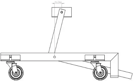
I attach the prospectus. because I had to reduce the image I do not know if the quota is legible, however the distance between the center of the hole of the two pins is mm.36,24
 

Attachments

  • Carrello posteriore - prospetto.webp
    Carrello posteriore - prospetto.webp
    7 KB · Views: 20
It seems a little close!
As you do, I care that the bike stands on the half-carry of the team, I would marry her so that all the possible surface of support is rubbed off the fulcrum perhaps reducing the angle of the lever.

another thing:
Shouldn't you leave some space to slip the foot under the lever to cut it off? ?
 
attached the video of the cinematism. It is important that the point of application of the force of the bike reaches the right side as well as from your scheme, so that the lever leans on its end.

constraints with cinematic analysis as a sleeve. contact between lever and frame with modified impact parameters.
 

Attachments

It seems a little close!
As you do, I care that the bike stands on the half-carry of the team, I would marry her so that all the possible surface of support is rubbed off the fulcrum perhaps reducing the angle of the lever.
even if the bike does not lean on the half-cart, the force of the pin is at that point, so it does not mean anything if the center of the bike is at 1 km.

Moreover it would be good to put a safety plug to put when the lever is lowered to prevent someone accidentally activate the unlocking system.

You actually don't have the space to rearm the system.
 
It seems a little close!
As you do, I care that the bike stands on the half-carry of the team, I would marry her so that all the possible surface of support is rubbed off the fulcrum perhaps reducing the angle of the lever.

another thing:
Shouldn't you leave some space to slip the foot under the lever to cut it off? ?
the rear fork of the bike, being of rectangular section, does not rest on a single point of the platform but on the whole surface.
 

Attachments

  • Tdm1996 PS 06 med_tcm71-220989.webp
    Tdm1996 PS 06 med_tcm71-220989.webp
    154.2 KB · Views: 15
even if the bike does not lean on the halfway, the strength of the pin is at that point.....
It's true! if the team is free to rotate does not transmit pair.
I said a caxxata:biggrin:
 
It's true! if the team is free to rotate does not transmit pair.
I said a caxxata:biggrin:
Of course! the bracket is free to rotate to adapt to the inclination of the fork that is not perfectly parallel to the floor
 
Forgive my ignorance in motion: eek: the photo has cleared me ideas!!!
Therefore if the fork is not horizontal you must try to estimate a maximum inclination and verify that the direction of force does not exceed the fulcrum.
 

Attachments

  • Carrello posteriore - prospetto.webp
    Carrello posteriore - prospetto.webp
    9.7 KB · Views: 16

Forum statistics

Threads
44,997
Messages
339,767
Members
4
Latest member
ibt

Members online

No members online now.
Back
Top