• This forum is the machine-generated translation of www.cad3d.it/forum1 - the Italian design community. Several terms are not translated correctly.

table of a body created with loft

  • Thread starter Thread starter gianmarco_h501
  • Start date Start date

gianmarco_h501

Guest
Good morning, everyone.
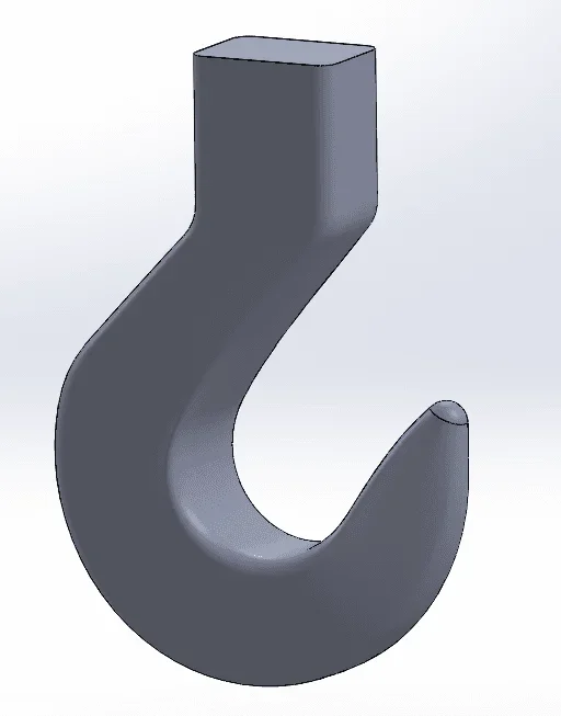
I have to draw a lifting hook and I found a problem that I can't fix.
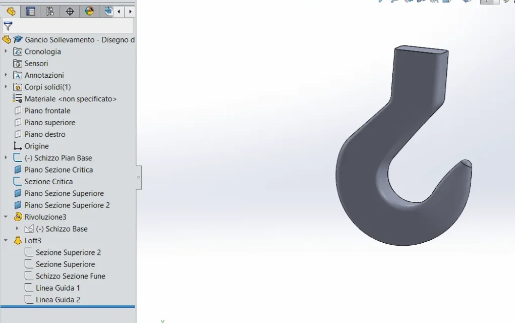
The procedure I adopted was as follows:
- basic sketch design (top)
- design of the various sections
- extrusion with loft with guidelines

all right here, the problem is when I go to table the hook. I practically can't quote anything, it's like he had joined the guidelines I gave him on the loft creating a spline, a unique line. For example when I want to go to quota the 30mm connection radius, select all the guideline and not only the radius.
the only way that comes to mind to solve is to quote the basic sketch, but in that case I can not remove all the construction lines that I created in the design phase.
I also don't know how I can combine the tip's "cupola" with the rest of the body so as not to show that annoying edge.
I attach some photos and the file to make you understand better.1586845611280.webp1586845473613.webp1586845774996.webp
 

Attachments

the only way that comes to mind to solve is to quote the basic sketch, but in that case I can not remove all the construction lines that I created in the design phase.
Why do you need to remove lines?
visualize the sketch, hide the body and quoti, then display the body and hide the display of the sketches (attention, n on hide the sketch, but its display from display menus>hizzi.

clipboard on modeling:
sketches must be simple and easy to manage for any changes.
4 ray inserted in all profile sketches are bad in management optics because it implies the modification of each single sketch or besides the fact that I listed each radius separately so if you have 3 profile sketches you have to change 12 quotas.
Moreover if for some reason, even drawing, you have to delete the radius on this way you can not do it.
managing the rays as a function to itself is much more practical and simple.
Thank you so much for the answer! I actually couldn't figure out how to hide the display of the basic sketch. In this way there should be no problem to quote flat geometry and various sections.
but you create an additional problem: how do I quota the edges that combine the upper section with the most critical one? I'll get you a picture to make you better understand.
Are these edges necessary for the complete definition of solid? or are only the flat quotas and quotas of the various sections necessary?
for example the tilt of the orange edge I can not quote it, solidworks tells me "impossible to convert selected entities in a line or in a circular arc"
Thank you very much
1587017986817.webp
 
Thank you so much for the answer! I actually couldn't figure out how to hide the display of the basic sketch. In this way there should be no problem to quote flat geometry and various sections.
....
I can't change my post, but for example I found the following image that refers to uni4395, so I wonder but do I actually need quotas from a higher view? 1587022092867.webp
 

Forum statistics

Threads
44,997
Messages
339,767
Members
4
Latest member
ibt

Members online

No members online now.
Back
Top