• This forum is the machine-generated translation of www.cad3d.it/forum1 - the Italian design community. Several terms are not translated correctly.

the humble servant

  • Thread starter Thread starter Fulvio Romano
  • Start date Start date
controllerso far we have talked about the manipulator. Now let's start talking about half the robot's thinking, the controller.
the controller, which is purchased along with the manipulator, is the electronic part that deals with engine power, feedback data management, etc. we see what elements it is composed of.
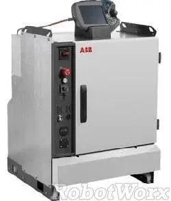
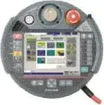
Wardrobe closetThe cabinet is the electrical panel that contains the electronic part. outside has an emergency fungus, a key mode selector (obligatory according to the norm), often a operating counter, and connectors for external devices. often has an ethernet socket and a usb port for connecting peripherals.
inside, the closet consists of the following macroblocks:
computeran industrial pc deals with the real control of the manipulator. it implements the algorithms of cinematic inversion, control, the interpreter of the programming language, the management of the peripherals, etc. in practice it deals with the logical management of everything concerning the robot, excluding the security. These are handled via hardware by a specific card.
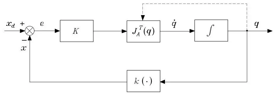
Cardboardthe axis card takes in the input references of position, speed and acceleration that the computer decides should have the engines, and also receives the data of the robot's ownceptive sensors (encoder or resolver). the difference between the two is the so-called " mistake" according to which it is necessary to pilot the engines so that the movement of the robot is the one wanted, that is the error is kept within an acceptable threshold. Actually part of the control is carried out by the pc, and it starts from the boards tab, but for a more detailed description I will try to write something further there. it will not be simple without introducing concepts of automation and control, but the attempt is obligatory.
drivesdrives are the devices that physically feed the engines. receive signals from the axle board and translate them into engine power.
 

Attachments

  • irc5_Chiuso.webp
    irc5_Chiuso.webp
    7.2 KB · Views: 12
  • irc5_Aperto.webp
    irc5_Aperto.webp
    92.1 KB · Views: 4
  • KRC.webp
    KRC.webp
    5.5 KB · Views: 12
selettore di maneraAs prescribed by law, robots always have a key hardware mode selector. the selector has mainly "automatic" and "manual" functions, plus other accessory, comfortable functions, but not explicitly required by the legislation.
automatic mode is the one in which the robot performs its working cycle independently, without supervision. It's the classic mode of operation.
manual mode is the one used during programming. in this phase, in fact, the programmer must have the possibility to stay safe near the robot. in this mode, in order to make the robot work, it is necessary to have in hand the teachpendant (see after), it is possible to work with part of the bypassed protections, and the maximum speed of the manipulator is reduced (chopped) for safety.

other modes can be:
"100% manual" in which, even in manual mode, the robot can go at maximum speed. can do so for a limited period of time and keeping certain buttons pressed. this function is useful in tasks that if run at reduced speed can have different results, such as painting.

some robots to be supervised by an external controller, such as a plc, must be placed in a specific "supervisioned" mode, which from the point of view of the legislation coincides in everything and for everything with automatic mode.
safety safetyWith regard to safety, industrial robots provide a card with certain inputs. the current legislation imposes for the robots a safety of (minimum) category 3, that is a system that remains safe in case of (single) failure, and that it is able to autodiagnose (where possible) such failure. this safety is achieved through the so-called "double circuit", or two physically separate channels that bring the same information. until the two channels remain synchronous, the information is considered reliable, when instead the two channels are in contradiction, the system stops and signals a failure to the security chain.
a fairly simple example can be an emergency fungus with two contacts, each of which arrives at the robot controller. if the two contacts are closed (not pressed) the robot is free to operate. if the two contacts open (fung pressed) the robot stops. if one of the two contacts fails, then the controller sees the two channels one open and one closed, understands that there is something wrong, stops the robot and reports the failure. to restore the fault it is necessary to open and close the two contacts simultaneously, to "demonstrate" the controller to have solved the problem. if you then cut both cables, the controller is not able to diagnose the failure, but in any case it ends in a safe state because it confuses the failure with the fungus state pressed. This is why the contacts must be opened. if it were the opposite, in case of cutting the cables the controller would interpret the fault with "non-pressed smoke" and would end in an unsafe state, contrary to the requirements of category 3 safety.

the robot control card does exactly this. takes in a series of safety signals and decides whether or not to cut the engine power. the decision is made via hardware because so reliability is greater than if it was made via software.

two types of emergency are made available. the so-called "emergency stop" and "autostop".
the emergency stop, typically, but not necessarily, associated with a fungus, cuts the power of the engines regardless of the state of the robot. the automatic stop instead behaves like the emergency only when the robot is in "automatic" mode. In "manual" mode, the robot ignores this type of emergency. It is the case, for example, of access doors to a segregated area where the programmer can operate the robot in manual even open doors.

as required by law, when a stop comes into operation, to restart the robot it is necessary to remove the cause of the emergency (leave the fungus, close the accesses, etc.) and then reset the error voluntarily.
Otherother controller elements are power terminals, input transformer, etc. etc.
 

Attachments

  • Selettore Modo.webp
    Selettore Modo.webp
    6 KB · Views: 86
teach pendandt"teach pendant" is the common name with which reference is made to the programming keyboard. each manufacturer then uses its own name "flex pendant" or "kcp" etc.
the teach pendant serves for the programming of the robot. Although particularly complex software is commonly written and tested to the PC with specific software, the teach pendant is however indispensable for changes in the field, for manual handling of the robot, for operational testing of programs, etc.

depending on the costructure design can change heavily, but in principle it consists of the following parts:
screenthe teach pendant matches a display on which you can see the program code and navigate between the menus. some manufacturers have a very comfortable and robust touch screen display, specific for industrial environment.
emergency emergencythe teach pendant always mounts on board an emergency fungus. This is imposed by the legislation, which prescribes a fungus in every workplace, and the tp represents a mobile workplace.
some manufacturers have the key mode selector on teach pendant. Unfortunately not everyone has it while being extremely comfortable, especially when working near the robot in the field and the controller is in the square room, maybe on the upper or lower floor. if the selector is on the picture, switching from automatic mode in manual and vice versa means making stairs, stairs and still stairs.
joystick or motion buttonsthe robot can be moved by performing the program, but obviously it must be possible to move it also manually to take it to the desired position, and maybe then record in the program such position. to do this there is a set of buttons, and very often also a jostick. there are multiple modes of movement, for example in the joint space, then "move axis 1" or "move axis 2", or in the operating space, for example "long advance x", "long rise z", etc. you choose the mode of time more comfortable.
tastieraif the screen is not touch screen, the teach pendant has a real qwerty keyboard. for those instead with the touch screen it is monitored, and the physical buttons limit themselves to the "play" of the program, to the "stop", to the "pause", to the function keys, etc.
useless to say that I personally find those with the touch screen much more comfortable.
hold-to-runis the most important button on board a flex pendant. When the robot is moved in manual mode it is vital that the programmer, enabled to be inside the robot's risk zone, remains conscious and able to intervene promptly on the robot at any time. during the movement of the robot, through the execution of the program or the movement with the joystick, it is necessary that the programmer has in hand the teach pendant, so as to be constantly able to intervene and stop the robot if necessary. he must then hold the hold to run button (also called "dead man") in the middle of his race. if you lay the teach pendant, or you run it by hand, or stumble, or faint, the hold to run button is released and the robot stops immediately. if it is stained and the tetanization of the muscles of the hand make it contract, the button is pressed to the bottom, stopping the robot in any case.
connection to the controllerthe teach pendant must of course be connected to the controller. typically the connection is formed by an ethernet cable for the display (which is actually a small indusrial pc), and a series of corders for the emergency fungus, the modal selector etc.
There is only one case of a well-known Italian robot manufacturer that offers a teach pendant wireless. There are those who speak well, and those who speak badly. certainly it is undeniable the comfort of not having cables between the feet that twist and fill with dust, but it must also consider negative aspects. first of all the weight. work for hours with a teach pendant that weighs twice as much as a wired I assure you that also makes shoulder and elbow. and then the batteries are discharged and recharged. Of course, the batteries last 8h (when buying!), i.e. a turn, and then there is the spare pack. camera batteries last even more, but how many times did you find them discharges just when you needed them? and in this case if you download the batteries, the emergency fungus is virtually "premute", stopping the robot.
 

Attachments

  • FPU.webp
    FPU.webp
    3.7 KB · Views: 86
  • KCP.webp
    KCP.webp
    12.7 KB · Views: 16
  • Fanuc_Teach_Pendant_A05B_2301_C301_View1.webp
    Fanuc_Teach_Pendant_A05B_2301_C301_View1.webp
    24 KB · Views: 13
  • R56TB_Teach_Pendant_opt.webp
    R56TB_Teach_Pendant_opt.webp
    5.6 KB · Views: 12
calibrationin post #66 I introduced the concept of "calibration" of a robot, saying that in reality there are three types of calibrations. the three types actually have different purposes and they do differently.
counterfeitingis the easiest calibration, which is normally performed several times during the life of the robot, even not due to damage. As mentioned above, the joints have quite high reduction ratios, this makes it that even for a few steps of the coupling, the engine, and therefore the encoder/resolver can make several turns. to know the position of the joint therefore it is necessary not only to know the position within the round, with the encoder or the resolver, but also to take into account the number of turns made in one way or another. the robot has a special electronic card whose task is precisely to record and keep stored by buffer battery, the number of turns made by each engine.
Sometimes, however, it may happen that the robot gets a hit, or is dragged by external forces at excessive speed, or is still dragged when it is disconnected from the controller, or the controller is off. in these cases the controller "teme" that its knowledge of the manipulator's position is no longer sufficiently accurate. then, in order to avoid the robot moving on wrong positions or even going to crash on the mechanical ends, the controller "loss" the counters.
at this point the robot can no longer move if not manually at low speed. must be "recognized."
to do so it is enough to bring the manipulator "to heel", or with all the joints to zero. no big precision is required, because it is sufficient that the joint is on the "zero spin", but it is not necessary that it is actually at zero angle, as within the round, the angle is however known.
depending on the type of robot there are different techniques to "put it in heels". Some builders use simple goals, others for tastators. In any case, after tacking the manipulator, you give a command of counter reset, and the robot is again usable.
calibration of jointsThis type of calibration becomes necessary when it is replaced, or however disassembled a motor, a reducer, a resolver, etc., i.e. whenever the reference of the coupling angle (and not only the current lap) is lost. to do this are necessary external devices, because greater accuracy is required than the calibration seen at the previous point. one of the methods is the following. for some robots, on each arm is made a machine-worked pitch whose plane is in close tolerance with the reference plane of the arm itself, for example the passing one for the axes of the joints at its ends. a differential inclinometer is used, that is a machine consisting of two inclinometers and that returns the angle between them. both are rested on the pitch of the link 0, that is the base of the robot, and the zeroing of the differential is done. then one of the two is carried on the pitch of the link 1 and the joint is rotated until the inlineometer marks 0, at this point the resolver of the axis 1. and so on finely calibrating all axes.
at the end of this procedure, in addition to the counters, the "zeri" of the resolver, or is communicated to the system what is the angle that must consider as zero. These calibration parameters are then saved in a file inside the controller.
other calibration techniques see the use of tastators that are mounted on specific locations on the arms. the "free" tastator of the calibration pockets that replace the worked pitches seen before. with the use of a tactor and an automatic procedure, the robot searches for the notch and auto resets.
Although this method seems simpler, there are at least two contraindications. the first is that the meter, as it is realized, has a precision less than that of the inlineometer. the second, much more important is that in this case the azeration of each joint between the arm that precedes it and the one that follows it, thus accumulating the error of measurement. with the use of the differential inline meter instead each arm is compared with the base of the robot, the extent of the error remains stable along the structure of the manipulator.
manipulator calibrationthe calibration of the manipulator is usually done, once only in the life of the robot. is made in the factory, and in theory it must be repeated when the fusion of an arm is replaced, which is quite rare.
the purpose of this calibration is to obtain the parameters of the arms. according to the notation of denavit-hartenberg (which I will explain in the next post) each arm has four independent parameters, of which three constants and one variable. If the variable is calibrated by the method described at the previous point, the three constant parameters must be obtained using a specific technique.
to carry out this type of calibration it is necessary to equip the robot of a tool that can be pointed, that is, whose position can be made known in space (e.g. dimensional) with a resolution at least one order of magnitude greater than that which is intended to be realized for the robot. There are several methods for identifying in the space of this tool, from the use of cameras and specific targets on the tool, to the use of real theodolytes, optical or electronic.

18 positions, arranged in such a way that the effect of no parameter is "hidden" by other parameters. to understand, if I acquire all positions that do not require the movement of the joint n, the identification of the parameters of the arms adjacent to this joint will be impossible or at least not precise.
In fact, many more than 18 positions are acquired, a system of overriding equations emerges, which is resolved at the minimum squares.
 
All clear?
Nobody asks questions? Are they extremely clear or extremely boring?
:smile:
 
All clear?
Nobody asks questions? Are they extremely clear or extremely boring?
:smile:
boringly clear or clearly boring??? :biggrin:
I'm just kidding.
Keep going. often is worth the "silent silence".
I'll tell you why upstairs and below... I often wondered if I was talking alone. :confused:
going then to see the number of visits of the discussion it seems clear that many read without asking questions.
However you do not write to prove something but, for the passion in what you do (at least for me it is so and I also believe for you).
I publicly renew your compliments for your exposure.
also because I have already broken the "browns" with my questions.:biggrin:
 
It will not be easy to talk about this subject. I want to be able to describe the juice of the matter without losing me in mathematical details. Of course, if anyone has to be interested, all you have to do is ask.

the purpose of all this discussion is to describe, possibly in a computationally simple way, the cinematics of a manipulator. in practice you want to move from the joint space to the operating space (direct kinematics) and vice versa (inverse kinematics). The geometric approach, as we will see, is neither simple nor mathematically robust, but in any case the first problem to deal with is to establish a notation for the description of cinematics.

jacques denavit and richard scheunemann hartenberg faced and solved for the first time in an organic and structured way a methodology for the treatment of open and closed cinema chains, but without multiple links. Moreover this methodology works only in case of rotary or prismatic joints.
the first thing to do is to assign solid reference frames to the various arms. Although theoretically it is possible to assign these frames oriented in any way, using the notation of denavit-hartenberg you can establish terne in a unique way, and that allows to automate the next steps.

- identify and number joint axes whose directions are z0, zn;
- choose a base terna [X0, Y0, Z0] fixed;
- choose zi giacent along the axis of the joint i+1
(ii) the origin of the i-th terna, the intersection of zi with the normal commune (rected at a minimum distance) to axis zi-1 and zi. if the axes are parallel and the axes are rotating, position or so to cancel d(i) (see later what is d(i)), while if it is prismatic, choose or in correspondence of a reference of the joint stroke, for example a end run;
- we call the intersection of the normal commune with zi-1
- fixing the direct xi axis along the normal common axis zi-1 and zi with positive direction from the joint i+1;
- the yi axis must be chosen to complete a levogira terna.

and if the minimum distance is not defined?
- if the axes are parallel, the point oi can be taken at a point to please.
- if the axes are accidents, the point is chosen at the intersection point.

the second thing to do is to compile the so-called "denavit-hartenberg table", that is, for each link the following parameters must be compiled:
- a(i), or link length: distance between oi and o'i.
- d(i), or joint distance: coordinated by o'i on zi-1
- alpha(i), or link twist: angle between zi-1 and zi around xi
- Aunti), or angle of joint: angle between xi-1 and xi axes around the zi-1 axis. in the case of rotary joint, this angle is the joint variable.

once the four parameters are obtained for each link, the structure is fully characterized. I will not write matrices, but it is easy to guess that to overlap the terna i with the terna i+1 I must translarla of "d" and "a" and turn it of "teta" and "alpha". It is therefore possible to write four matrices, two translations and two rotations. multiplying among them these four matrices is obtained a matrix to(i)(i+1) of rotation that allows to move from the joint i+1. at this point you understand the advantage of the notation of denavit-hartenberg. In fact, respecting this convention, the matrix has a fixed structure, known for any cinematism. it is therefore not necessary to obtain it every time.

from the operating point of view therefore, once you notice the table of denavit-hartenberg, you just "compile" the various matrices a.

By multiplying the various matrices to each other, a total matrix of the whole manipulator is obtained, describing the orientation of the tool terna compared to the base terna. What do I need? Let us imagine that the manipulator has "in hand" an object. this object will be identified by coordinates with respect to the terminal organ, fixed, because the object is in solidarity with the terminal organ. if I multiply these coordinates for the matrix t, I get the coordinates of the object compared to the base terna, that is to the world.

So here is solved the problem of direct cinematics, i.e. insert the angles of joint in the matrix t and I get the position of the tool regarding the base.
 

Attachments

  • DH.webp
    DH.webp
    28 KB · Views: 10
Last edited by a moderator:
All in all, direct cinematics does not involve big problems. and if the denavit-hartenberg methodology provides a secure track on which to move, you can still use different approaches, especially for simple geometries, to solve the problem.
It is not so for reverse cinematics. the matrix t is an extremely complex trigonometric matrix. it is therefore not interesting to try to reverse the function:

x = t(q)

where q=(q1, q2, ..., qn) is the vector of the joint variables and x = [p, fi] = [(x1, x2, x3), fi) è il vettore posa (= posizione + orientamento) nello spazio operativo. Perché non esplicito il vettore orientamento fi? Beh...lo vedremo tra un po', non è così ovvio.

Dunque, se l'equazione scritta sopra è quella che descrive la cinematica diretta, la cinematica inversa può essere scritta così:

q = k(x)

E' un'equazione estremamente complessa, fortemente non lineare, può ammettere soluzioni multiple in talune situazioni, in altre non esistono soluzioni ammissibili. Sebbene quindi in alcuni casi possa risultare intuitiva, essa NON viene ricavata in forma chiusa se non per strutture estremamente semplici, come i manipolatori planari a più bracci.

differential kinematicsLet's see something right away. If I have a prismatic joint moving at x speed, its end will move at x speed. If it moves to 2x, the end will move to 2x. If instead I have a rotating joint that rotates at angular speed w, the end will move at speed w*r. If it rotates to 2w, the end will move to 2w*r. It seems obvious, but as simple as it is the key to differential cinematics.
we want to find the position of the tool according to the joint variables, but if we look directly for this position, non-linear, unstable and complex equations come out. we have just seen instead that if instead of position, we fix attention on speeds, the problem becomes suddenly linear.

then decide to write a new matrix. as this matrix will contain speed rates, i.e. the derivative of what we really are interested in, i.e. the position, we will call it "Jacobiano". we are therefore looking for such a matrix so that it is possible to write such an equation:

x’ = j(q) * q’

where x' = [p', w] is the speed vector (speed and angular speed) and j is the jacobiano (geometric). the symbol <'> represents the derivative of the variable/vector time. Sorry, but here on the forum I can't put the dot over the letter.. .

By reading the above written equation we understand that each element of the matrix j represents the contribution of a joint. In fact, if we express the matrical development we obtain:

== sync, corrected by elderman ==
vy = j21*q1 + j22*q2 + j2n*qn
...

but how to write individual jab elements?

I do not write formulas, which I will post on request, but the concept is as follows:

for a prismatic joint each joint provides the following contributions, and therefore the corresponding jab:
- the angle velocity of a joint compared to the previous one remains equal;
- the linear speed of a joint compared to the previous one is increased in the direction of the axis of the joint.

for a Rotaid joint instead:
- the angular velocity of a joint compared to the previous increases of q';
- the linear velocity of a joint compared to the previous one increases q' for the length of the arm.

the shares written here are relative to each joint compared to the previous one. the direct cinematic matrix t(q) that we saw before it is possible to bring all these elements back to the terminal organ.
Ultimately we have built a j(q) matrix with the various rates of joints to the different speed components in the operating space, written compared to the terminal organ.

Good. but we were interested in the position, and not the speed... so?
 
we immediately say that the fact of writing differential cinematics in linear form, does not mean that its inversion is carried out in closed formula. once again in fact the concept of having a formula, making calculations and getting a result, is not winning. There are very robust and little heavy techniques from the computational point of view.

we see an interesting algorithm, which is based on the reverse of the jacobiano.
the formula to "invert" is:


therefore, we can multiply on the left both members for the reverse of j:


In principle it is possible to write an algorithm that, starting from the current position of the manipulator, calculates j(q), reverses it, multiplies it by x’ and gets q’. integrating (summating the various steps) then the various q’ you get the vector q of the required joint variables.
seems to work, but there is a problem. in each step of the algorithm is used the q vector of the previous step, and the x vector of the current one. this inconsistency leads to an error, which long to go can start a numerical drift and become, at regime, meaningful.

to overcome this problem a different algorithm is adopted. first, we define the error as a difference between the desired position and the current one:

e = xd – x

and resulting from time:

e’ = xd’ – x’

the purpose of the algorithm is to bring to zero the error, at least to regimen.

suppose to write the following equation:

(xd' + k*e)

replacing what we wrote before, the following equation comes out:

is + k*e = 0

It means that the evolution in the time of error is such that it cancels at regime, of course if the k matrix is defined positive, for example it is a diagonal matrix.
so if we use an algorithm based on this formula, we avoid a drift of error and ensure asymptotic stability.

a block scheme that represents the implementation of this algorithm is shown in the figure. These types of schemes are quite familiar to those who bazzica matlab and simulink, we try to explain it.

is nothing but a graphic representation of a cyclic algorithm. during a step of execution, we have the xd size, that is the "set point", the laying value that we want the manipulator to reach. to this we go to remove the current pose. this is calculated by taking the coupling variables of the previous step (see that the arrow goes "against current") and by direct kinematics (then by multiplying the matrix t) the current laying is calculated.
after the sumer node comes out xd - x = and, the difference between the desired position and the actual position, that is the error.
error (the error vector) is multiplied by a k matrix. varying the values of this matrix you can change the behavior of the algorithm.
then we have the value "k*e" that enters the sumer node together with x'd, or the speed you want. this magnitude can be simply derived from the desired xd position over time.
multiplying again by the reverse of the jacobiano we finally get the following formula:


that is what we had established to be the basis of the algorithm. We integrate what, that is, we put it at the result of the previous steps, and we get q.

I'm done. without having to reverse any formula, with a simple recurring algorithm we managed to get q from xd, i.e. We solved the reverse cinematics!This q value is used with direct kinematics (matrix t) to calculate the x to be fed to the next cycle of the algorithm, and also to calculate the value of j(q) which as we have seen is function of q.

Guys, I swear I only used the strictly indispensable math. . But it was worth a little detail, wasn't it?
These methods of filtering convergent algorithms are studied in very few faculties, yet, once they are well understood, they are a grimaldello that can be used to solve problems otherwise uncompromising. I would study these topics immediately after analysis ii, and make them mandatory for all engineering addresses.
 

Attachments

  • Inversa-J.webp
    Inversa-J.webp
    7.8 KB · Views: 11
rest a bit with all these posts.

Write a nice text of robotics elements, or mechatronics and make it free, for the users of the forum, that interests me.
 
I like it. as pier says: give us in bad! :biggrin:
Guys, I swear I only used the strictly indispensable math. . But it was worth a little detail, wasn't it?
Of course, keep going!
These methods of filtering convergent algorithms are studied in very few faculties, yet, once they are well understood, they are a grimaldello that
can be used to solve problems otherwise unsafe. I would study these topics immediately after analysis ii, and make them mandatory
for all engineering addresses.
would be a good idea to do an advanced inspection course for all engineering addresses. even if, in my opinion, remains the usual problem
of the Italian university: so much theory but little practice. Perhaps in the future, with the experience on the field, can be an advantage. Maybe. For example, to me,
Because of the fact that I haven't seen these things yet, something is not so clear. Suppose I have my nice robot and I wanted to
implement the jacobiano reverse algorithm you showed. How do I do that? how do I translate that block diagram (or many others I studied) practically? I am still unclear how to really accomplish them.
 
Suppose I have my nice robot and I wanted to
implement the jacobiano reverse algorithm you showed. How do I do that? how do I translate that block diagram (or many others I studied) practically? I am still unclear how to really accomplish them.
qui find the description of the controller.
the controller houses an industrial pc that deals with these problems called "centralized", because they require a global analysis of all joints.
on the pc is installed a realtime operating system (= deterministic), typically linux, qnx, vxworks, etc., and turns a control software. the control software, is responsible for creating the above algorithm, i.e.:
- takes information from the axle control board
- runs a cycle
- generates setpoints for the axle control board.

the cycle can be similar to the one written below in metacode:
Code:
start

read more <posizione desiderata=""> from <pianificatore di="" traiettorie="">read more <giunti attuali=""> from <scheda seriale="">calculated <velocità desiderata=""> through <derivazione> of <posizione desiderata="">calculated <posizione attuale=""> through <cinematica diretta=""> of <giunti attuali="">calculated <jacobiano> through <struttura jacobianto=""> of <giunti attuali="">and <posizione desiderata=""> - <posizione attuale=""><temp> = k * and + <velocità desiderata=""><setpoint ai="" giunti="" velocità=""> ♪ <temp> * <jacobiano><setpoint giunti="" posizione=""> ♪ <setpoint giunti="" posizione=""> + <setpoint ai="" giunti="" velocità="">write <setpoint giunti="" posizione=""> up <scheda assi.="" controllo="">back to the beginning</scheda></setpoint></setpoint></setpoint></setpoint></jacobiano></temp></setpoint></velocità></temp></posizione></posizione></giunti></struttura></jacobiano></giunti></cinematica></posizione></posizione></derivazione></velocità></scheda></giunti></pianificatore></posizione>
 
Okay. This at high level. But if the controller wanted me to do it? I'll explain. Suppose we have only n ( suppose n=6) members connected to each other with rotating or prismatic pairs. Suppose I have all the sensors I need, etc. I decided my law of control. now, how do I realize it at low level? i.e. how do I make it electronically (or analog or digitally)? the reasoning I do is the following. in siso systems (both analog and digital) I have a system that I want to control in retroaction, I calculate my transfer function (or with laplace or z-transformed) that allows me to control the system as I want, then I step to the realization of a circuit (or with analog components or with a micro) that has the same transfer function that I chose and I go to place it in the control loop, before my system to control. in the case of our robot (with only 6 poor pieces of iron connected to each other), which is still a system (although mimo), how do I realize all this?
 
Okay. This at high level. But if the controller wanted me to do it? I'll explain. Suppose we have only n ( suppose n=6) members connected to each other with rotating or prismatic pairs. Suppose I have all the sensors I need, etc. I decided my law of control. now, how do I realize it at low level? i.e. how do I make it electronically (or analog or digitally)? the reasoning I do is the following. in siso systems (both analog and digital) I have a system that I want to control in retroaction, I calculate my transfer function (or with laplace or z-transformed) that allows me to control the system as I want, then I step to the realization of a circuit (or with analog components or with a micro) that has the same transfer function that I chose and I go to place it in the control loop, before my system to control. in the case of our robot (with only 6 poor pieces of iron connected to each other), which is still a system (although mimo), how do I realize all this?
Hey, give me time, I haven't gotten to control yet. we have arrived at the cinematics, we still have to talk about direct dynamics, reverse dynamics, independent controllers to the joints, centralized.... we are preparing analyses ii and we arrived at the algebra...:tongue:

the architecture of the controller is the one described above. as command organs from there does not escape, also because it is more or less standard architecture for the whole world of motion control.

the algorithm of cinematic inversion "absolute" to a control in retroaction, not for nothing, because it was born from the mind of controls. but it is not a control. in a control scheme there is a system to control and a controller that generates references, here instead we have nothing to control, but only an algorithm to converge.

Since you're talking about transforming, we're trying to get into a little more mathematical detail. I suggest that in theory we can use laplace to simplify the model and analyze its stability, but more correctly it would always be used zeta because we always have to deal with digital controls, and therefore at a discreet time.

That said, I threw there a pretty deep concept, but without unvising it. when I talked about k, that is the multiplier of error, I said it must be a "positive defined matrix". Why?

In particular, I need positive real values, because, from an energy point of view, the asymptotic stability of the algorithm can be seen as a question of balance. We said that the primary purpose of choosing this algorithm is to represent a differential equation of evolution of error in the space of time that is nothing at regime.
As you can see, I'm not talking about poles and zeros, just because we're not talking about a system of control, but simply an evolutionary algorithm. the beauty of this algorithm is that, if it is represented from the energy point of view, it must obey the theorem of lyapunov.
the evolutionary function of the error is precisely a candidate function of lyapunov, and being k a constant and defined positive matrix, the balance is globally attractive.

At this point, I also tell you the algorithm with the transposed jacobiano, which is even more interesting mathematically, although it has lower performances.
 
to reconnect to what was said before, let's try to see this other algorithm. I had decided to leave him, but since someone interested, let's see how to describe him.
the use of the reverse of the jacobiano works substantially because the reverse of the matrix is the algebraic solution of the inversion of cinematics. the algorithm seen before is a method to ensure the convergence of a recurring count.

instead we see a simpler algorithm from the computational point of view because it exploits the transposition of the jacobiano. It is a question of finding a link between the speed to the joints and the error that the zero convergence of the latter does not require linearization. as mentioned, the stability of the algorithm is guaranteed by the theorem of lyapunov. We choose a square form as a candidate function of lyapunov that recalls a kind of potential defined in the space of error:

v(e) = 1/2 and (transposed) k and

where k is a symmetrical and defined positive matrix, for example diagonal. differentiating from time and remembering that x' = j(q) q' is obtained:

v' = e(transposed) k xd' - e(transposed) k j(q) q'

So, if we choose

q' = j(transposed) k and

we get

v' = e(transposed) k xd' - e(transposed) k j j(transposed) k and

if the speed reference is constant, then xd' = 0, v' is defined negative, while v was defined positive, then for the lyapunov the system is asymptotically stable.
If, instead, xd' should be different from zero, nothing can be said about the sign of the first term of the previous equation, then in principle the system would not be asymptotically stable. true, however the error can be kept small increasing the norm of small k., not null to regime, precisely for this reason we said that the algorithm with transposed is less performing than that with reverse.
inter alia k can not even be increased to dismistress, because the algorithm is implemented at a discreet time and you risk numerical instability.
 

Attachments

  • Trasposta-J.webp
    Trasposta-J.webp
    8 KB · Views: 4
Well, I did a short parentheses in math. I hope I have not too much feared the reader, but I would return to treat the arguments in a less rigorous way, but certainly more intuitive, leaving aside the mathematical formalism that, although of vital importance for those who have to use these concepts in practice, is instead only a series of boring letters for those who face reading with a romance spirit.
However, the call for more precise clarifications remains open to those who have curiosity.

Let's go back to talk about the jacobiano, because even for those who are convinced that the matrices are a way of dressing the laundry, can be intuitive what I'm about to say.
we said that the jacobiano, j[q(t)] represents the link between speed to joints and speed in the operating space of a manipulator. This matrix is full of meaning and instantly condenses a myriad of information on both the manipulator himself and his instant configuration.
jacobiano as applicationjacobiano can be considered as an "application", or a kind of "function" that does not have too many claims on domain and codomain. Let's imagine two sets. the first, q', is the set of all the speeds that can have the joints of a manipulator. we imagine a planar manipulator with two arms and two joints, which is a square in r2. along the riots the q1' velocities of the first joint, along the ordered q2' of the second joint. each point inside this square represents, with its coordinates, a couple of speed to the joints.
in another space, always r2, there will be another square, certainly with different shape, which instead represents the speeds of the terminal organ in the operating space. each point of the right square is the image of a point of the left square obtained through the jacobiano.
we try to abstract these squares until we get six-dimensional hypercubes. the substance of the matter does not change, but now we can describe what happens for a manipulator at six degrees of mobility and six of freedom.
the jacobiana matrix may have a "null", or a subspace of the left figure whose image falls in the "zero" point of the right one. in practice a speed set to the joints that does not involve any speed in the operating space. just imagine a spherical wrist in the singularity of wrist, that is with the axes 4 and 6 aligned. If axis 4 turns at a certain speed and 6 at the same speed in the opposite direction it has that the terminal organ remains firm. this "point" then certainly falls into the void of the jacobiano, which for the occasion (singularity) is also singular...but we see it at the next point. if it is very complicated to identify intuitively what are the speed sets that involve nothing in the operating space, it is rather simple enough, exploiting the theory of matrical calculation, identifying the void of the jacobiano. So this matrix tells us, with rigorous mathematical formalism, a very interesting first thing about the manipulator.
singularityWe saw what the singularities are. are positions of the axes of a manipulator from which it is not possible to obtain a shift to pleasure. for example in the planar manipulator to two arms, when these are aligned you have a singularity; For the manipulator it is impossible to make a movement along the arms, while he can only move orthogonally to them.
an anthropomorphic manipulator has two types of singularity.
- the shoulder singularity, when the pulse center is located at any point in the axis 1; in fact the manipulator cannot move in orthogonal direction on the plane formed by the first two arms.
- the wrist singularity , when axes 4 and 6 are aligned, and we saw it before.

What happens to the jacobian when the manipulator is in singularity? simple, it descends of rank, and therefore its determining is null, and therefore its reverse is not defined, and therefore still its null increases in size (those dimensions of how many points has dropped the rank).
Once again, a critical situation of the manipulator translates into mathematical criticality of the jacobiano.

in the shoulder singularity, if I have a rotation of the axis 1, the wrist center remains firm. jacobiano informs us of this by projecting all the axis one on zero of the velocity space to the joints.
redundancyWhat happens when I have a redundant manipulator? the jacobiano relates the velocities in the joint space and that in the operating space. but if the manipulator is redundant it means that the number of joints (j columns) is greater than the number of dimensions of the operating space (j rows) in which it is possible to move. Just imagine a robot with seven joints (7 degrees of mobility and 6 degrees of freedom), but also a planar manipulator with four arms (4 degrees of mobility and 3 degrees of freedom in the plan). What shape does the jacobiano take? simple, it is rectangular, and this means various things.
first, being rectangular, it is not possible to calculate the reverse. What does this mean from a physical point of view? if the Jacobin project the velocity of the joints in that in the operating space, the fact that it is rectangular, and in particular not invertible, means that at rigor there is no solution (univocal) of reverse cinematic. In practice, given a speed set in the operating space it is not possible to identify (univocally) a speed set to the joints that has it as a consequence. In fact, for redundant manipulators there are infinite sets of speeds to the joints to obtain a certain speed in the operating space (as long as this is within the image of j, of course).
for example we imagine a four-arm planar manipulator and imagine we want to get the speed in the operating space v = [0, 0, 0], i.e. fixed terminal organ. obviously there is the trivial solution q'=[0, 0, 0, 0] with all the joints still, valid also for non redundant manipulators, but the rectangular jacobiano 4x3 reminds us that for this redundant manipulator it is possible to have internal motions to the structure even if the terminal organ is firm. that is, there is no unique speed set to give the joints so that the terminal organ is still, but there are infinite ones.

Obviously the non-invertibility of the Jacobin does not mean at all that the problem of reverse cinematics is unresolvable. just add some extra bonds. not within the details, but it is possible for example to introduce constraints so that the manipulator does not impact with the arms against obstacles, or that the arms are held at the maximum possible distance between them, or even that the joints are as far away as possible from their ends, etc. etc. of "objective functions" whose optimization allows a unique solution of reverse cinematics there are bizzeffe. the most interesting however is the objective function that optimizes the speeds of the joints. if in fact instead of the reverse of the jacobiano we use the left pseudo-inverse:

pseudoinversasx (j) = [J(trasposto) * J ]^-1 * j(transposed)

We solve to the minimum squares the indefinite problem of reverse kinematics, thus obtaining as a result the trajectory in the space of the joints that realizes the desired speed in the operating space, having at the same time the norm of q' smaller than the infinite possible.
 

Attachments

  • J-Applicazione.webp
    J-Applicazione.webp
    7 KB · Views: 3
duality of cinetostasisanalyzing the elementary work accomplished by a manipulator and his joints during an infinitesimal shift it is possible to arrive at the following equation:

tau = j(transposed) * range

where tau is the vector of pairs to the joints, and range the carrier force in the operating space. resembles the equation:


Right? only that in the first member we have the world of joints, in the second real world. this particularity is precisely called "cinetstatic ductality". what is true for cinematics is the opposite ("inversion of worlds") for static.
we imagine the usual planar manipulator, we also imagine only two arms. if the two arms are such that the arm is large, both has a great speed (x') of the terminal organ. Therefore it means that, at equal speed to the joints, if in this position the speed is great, it means that it is great the norm of j. but then will be great also the norm of j (transposed). But then, at the same range, the tau will be great. therefore in this position it will take great couples to the joints to obtain even small forces to the terminal organ.
In essence we have discovered, what is intuitive, which in positions for which the manipulator has aptitude to generate great speeds, can generate small forces, and vice versa.
ellipsoids of manipulationcynetstatic duality can be seen geometrically with an elegant and interesting instrument, i.e. the ellipsoid of manipulation. In fact the ellipsoids, let's see why. This tool can be used both in the design phase of the robot to evaluate its dexterity, and in the planning stage of trajectory to understand if it goes into "poco destre" areas.

we are in the space of speed to joints. we imagine drawing a sphere with center origin and unitary radius (of course we speak of a hypersphere of size equal to the number of joints of the manipulator). we can write the equation of this sphere as a standard of speed equal to one:

* q' = 1

but as we know that v = j(q) q', then the above equation becomes:

v(transposed) * [J * J(trasposto)]#1 * v = 1

that is the geometric representation of a quadrica, for the accuracy of an ellipsoid (in size) defined in the space of speed in the operating space. through the mechanical structure of the manipulator, in short, the sphere "deforms" , "strengthening" in the directions where it has more aptitude to generate speed, and "contraendosi" in the opposite one. measuring the radius of the ellipse in a given direction can be measured by how much the manipulator is able to generate speed in that direction. The more ellipsoid looks like a ball, the more manipulator is able to generate speed in an isotropic way.
Moreover the volume of the ellipsoid (the determining factor of the nucleus of the square form, or det[J*J(trasposto)] ) by a measure of the total "dexterity" of the manipulator.
if the manipulator is in singularity loses of dexterity, and in fact the determining of the nucleus becomes zero, is the ellipsoid degenerates in a point.

Suppose we do the same thing, but instead of the speeds of the joints, we use the pairs. for similarities, the two equations become:

tau (transposed) * tau = 1
range(transposed) [J * J(trasposto)] range = 1

if before we talked about ellipsoid of manipulation in speed, now we talk about that in force. the same speeches made before, with the only difference that now the core of the quadrica is the reverse of the previous one. the ellipsoid of manipulation in force then will have the greater axis at the lower axis of the ellipsoid of manipulation in speed, and vice versa. as we had seen before, where there is greater aptitude to generate speed there will be less aptitude to generate strength.

the manipulator therefore can be seen as a "mechanical transformer" of speed and forces from the space of the joints to the operating space.

in the following figures you see:

1. comparison of the ellipsoids of manipulation in speed and strength for a planar manipulator to two arms in different positions.

2. comparison of ellipsoids for a three-arm planar manipulator. This resembles a human arm, and you can distinguish the two cases. In the first case we imagine writing on a sheet of paper. it is natural to support the elbow and write moving the wrist. manipulative ellipsoids show that in this configuration the manipulator presents in vertical direction the lower (or almost) axis of force ellipsoid, and in horizontal direction that in speed. In fact, the task requires fine control of the vertical pressure of the pen on the sheet, and horizontal speed to write with good spelling. having poor ability to generate strength or speed in one direction means having greater control.
the second case is always the human arm that for example must throw a bowling ball. here there is need for vertical direction force and speed in the horizontal one. the arm arranged in that way has exactly this attitude, as visible from the ellipses.
 

Attachments

  • ConfrontoEllissoidi.webp
    ConfrontoEllissoidi.webp
    28.5 KB · Views: 3
  • CompitiEllissoidi.webp
    CompitiEllissoidi.webp
    34.2 KB · Views: 3

Forum statistics

Threads
44,997
Messages
339,767
Members
4
Latest member
ibt

Members online

No members online now.
Back
Top