tvi71it
Guest
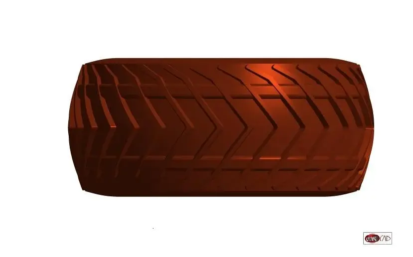
hi...the surfaces that you highlighted me, I would say of the bottom of the excavation, are in this example, a constant 5 mm offset, of the outside of the tire. .Yes! Yes! :finger: we have provided that the surfaces I have highlighted in the attached image are normal to the support surface. only after that I can tilt with a tot angle of stripes.
Hi.
tvi71


")