• This forum is the machine-generated translation of www.cad3d.it/forum1 - the Italian design community. Several terms are not translated correctly.

better solution to close a surface.

  • Thread starter Thread starter panormus
  • Start date Start date
I put in another critical area.. How would you close it?
 

Attachments

  • Cattura59.webp
    Cattura59.webp
    27.5 KB · Views: 12
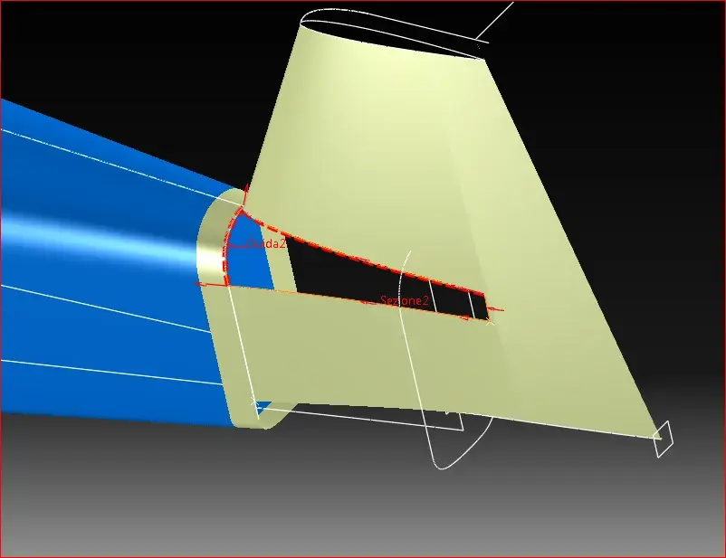
ma making in theme.. photo photo http://www.cad3d.it/forum1/attachment.php?attachmentid=30125&d=1353234436how would you close it? I'm not clear yet, sorry. :frown:

look at the area designed with the black marker "sup to create". . .
a surface for four edges ("square" in alias) for the four edges lined in green. a crop with curve to green dots (cut edge).
I put in another critical area.. How would you close it?
depends... what do you want to do?
I, without reading or writing, but knowing how to use the surfaces, would take the yellow one, I would select only the aft control vertices and scale them until the surface "enter" the tail*. at that point, intersection with the tail and see if the resulting curve is satisfactory.

(*)
practically the surface remains equal to the bow, but it must be narrowing to the stern, as if I crush it between the fingers.
 

Attachments

  • Cattura44.webp
    Cattura44.webp
    91 KB · Views: 8
for the first answer, it is not all that area I have to close but only that between the dot line you have done and the green line below, some starts from sx with a very recirculated trend to end to dx with a "retangle with bevelled edges" (I don't know how it is called).

for the second point in theory would be the best solution, but look in the annex what happens if I narrow the fuselage in the tail.
 

Attachments

  • Cattura60.webp
    Cattura60.webp
    26.2 KB · Views: 8
for the first answer, it is not all that area I have to close but only that between the dot line you have done and the green line below, some starts from sx with a very recirculated trend to end to dx with a "retangle with bevelled edges" (I don't know how it is called).
We're not here.
If you have to build a surface, in 98% of cases you will have to make it a bigger, clean, and then cut away what you don't need. I already recommended it a few posts ago (I think the #5).
If you dare to draw directly what you want to get, you will never get out.
for the second point in theory would be the best solution, but look in the annex what happens if I narrow the fuselage in the tail.
What's going on? that the cut in profile is tilted? means that you will have to shrink lower than the top. How much? until the cut comes as you wish.
that is what I suggested in the same post I recalled above, that is post #5.
 
[cut] some start from sx with a very recirculated trend to end to dx with a "retangle with bevelled edges" (I don't know what it is called).
Sorry, but I realized that in my post before it was missing a piece.
If you see, I suggest that you continue the cutting in the fuselage by also eliminating the part with the orange sampling. the reason is very simple. See the cyan curve? is obviously divided into two, a curvilinear tract and a straight one. you can't think of using this cyan curve as one of the four sides of the surface, it's one of the most trivial mistakes that you can make. to do so you should "unite" the two curves, and the edge would represent a discontinuity on the edge of the surface. There's gonna be a half-time junkie.
this is why the cuts in the surfaces must be regular, even at the cost of cutting more, provided then the surface that adds birth from four clean edges and with angles as close as possible to 90°.

Clear?
 

Attachments

  • Cattura44.webp
    Cattura44.webp
    87.3 KB · Views: 12
We're not here.
If you have to build a surface, in 98% of cases you will have to make it a bigger, clean, and then cut away what you don't need. I already recommended it a few posts ago (I think the #5).
If you dare to draw directly what you want to get, you will never get out.


What's going on? that the cut in profile is tilted? means that you will have to shrink lower than the top. How much? until the cut comes as you wish.
that is what I suggested in the same post I recalled above, that is post #5.
It is not a question of stubbornness, but of not knowing how to do, in fact I asked you an example, a video, photos.. that make me understand... I ask from post #6.
In addition, the bottom line of the cappottina is not found on the surface that you would create with the famous square alias... blah blah.. but it's more back and the hood has a circular section pattern.

regarding the second thing.. I understand what you mean, but we're dealing with aerodynamics, I'm not masterful of doing what I want. the profile of the rudder is a symmetrical profile naca0010 and such must remain from top to bottom.. It's not as simple as it looks.
 
.... but look in the annex what happens if I narrow the fuselage in the tail.
This happens because the final section of the fuselage you have outlined is not correct. in that aircraft the fuselage ends exactly in correspondence of the uncertainty of the rudder and its section therefore coincides with the vertical section (made compared to a perpendicular plan to the axis of the veil) of the tail impenage. in front of that section plan you will have the fixed drift, and behind the mobile rudder.
the lateral performance of the fuselage, starting from the tail and in the direction of the bow, must practically be the continuation of the bearing surface of the rudder in neutral position.
from the attached photo you better understand what I mean.
 

Attachments

  • su_26.webp
    su_26.webp
    51.9 KB · Views: 13
This happens because the final section of the fuselage you have outlined is not correct. in that aircraft the fuselage ends exactly in correspondence of the uncertainty of the rudder and its section therefore coincides with the vertical section (made compared to a perpendicular plan to the axis of the veil) of the tail impenage. in front of that section plan you will have the fixed drift, and behind the mobile rudder.
and that's what I'm trying to do, but taking into account that the profile must be the same throughout the length of the rudder.

the lateral performance of the fuselage, starting from the tail and in the direction of the bow, must practically be the continuation of the bearing surface of the rudder in neutral position.
from the attached photo you better understand what I mean.
and on this we are, I attach the view from above to show that the rudder is the continuation of the fuse. in fact I would like to make fuse stab and rudder and then cut all after making a master.
 

Attachments

  • Cattura61.webp
    Cattura61.webp
    8.7 KB · Views: 19
  • Cattura62.webp
    Cattura62.webp
    11.9 KB · Views: 12
and on this we are, I attach the view from above to show that the rudder is the continuation of the fuse. in fact I would like to make fuse stab and rudder and then cut all after making a master.
I see that of continuity between fuselage and vertical impennage there is very little... the fuselage is "stringe" too quickly, making a rather accentuated curve. in reality the flank of the fuselage is almost straight up to the helm
If you want to have the arrival section of the fuselage in the tail you have to get it from the binding section at the helm. I imagine that then you would be able to set the tangency between the end of the fuselage at that point and the continuation of the surface of the rudder.
 
I'm hard to admit it, but this time I liked you.
I think this is the solution in the tail, get the rudder section.
for the accentuated curvature I noticed a little compared to certain photos, but my design is faithful to a famous, very reproduced triptych and model 26mx.
I noticed that there are no two equal su26s if you look at them carefully. ,
 
what I managed to do until now.
 

Attachments

  • Cattura63.webp
    Cattura63.webp
    38.7 KB · Views: 11
  • Cattura64.webp
    Cattura64.webp
    24.8 KB · Views: 10
  • Cattura65.webp
    Cattura65.webp
    40.6 KB · Views: 11
  • Cattura66.webp
    Cattura66.webp
    15.5 KB · Views: 14
And here's the problem of the bloody cusp. . .

Yes, yes. I'm doing it again. As long as I don't have an appreciable result, I'm willing to question everything.
 

Attachments

  • Cattura67.webp
    Cattura67.webp
    20.4 KB · Views: 12
the fuselage is "stringe" too quickly, making a rather accentuated curve. in reality the flank of the fuselage is almost straight up to the helm
for the accentuated curvature I noticed a little compared to certain photos, but my design is faithful to a famous, very reproduced triptych and model 26mx.
we assume that the blueprints that are around are certainly not of origin of the sukhoi but of it is more or less faithful reproductions made for (or) the aeromodoellisti.
said this imho or the blueprint you are following or is right away from reality or the curves and profiles you have made do not follow the blueprint.
If you quart the attachment you will see that the flanks of the fuselage, in the plant, have an almost retiline pattern until the attachment of the rudder, different from your model.
Moreover the sections that represent the top of the fuselage are well different from what appears in your screens, where they look more like semicircles. in the annex see section f15 which is the terminal part of the tail and that in your model I do not seem to see. In any case, the side guide curves of your model (as long as you have used them) do not seem to me porprio that correspond to those of the blueprint.
I noticed that there are no two equal su26s if you look at them carefully.
boh, perhaps for some detail (ogiva, capottina...) but certainly not in the tail rudder and the main aerodynamic surfaces
 

Attachments

  • su26mx.webp
    su26mx.webp
    282.3 KB · Views: 12
And here's the problem of the bloody cusp. . .
Yes, yes. I'm doing it again. As long as I don't have an appreciable result, I'm willing to question everything.
I don't understand why you want to fill that hole with a surface that doesn't actually exist.
there is the horizontal drift and the upper lining of the fuselage is typically interrupted at the point that I indict you with the yellow arrow according to the lines added in yellow. after the horizontal binding is mounted, the fitting elements are added which have a different shape than the one you would obtain with the procedure you want to do. see the attached photo, where you see (not too well) the riveted element that collects vertical, horizontal and fuselage.

also the section of the helm where you indicate with "section2" is wrong. It's convex while it should be the perfect extension of the fuselage flank and also from the blueprints you can see that the shape is not the one you set.
 

Attachments

  • su26_coda_.webp
    su26_coda_.webp
    23.9 KB · Views: 6
  • coda SU26-2.webp
    coda SU26-2.webp
    134.5 KB · Views: 8
after the horizontal binding is mounted, the fitting elements are added which have a different shape than the one you would obtain with the procedure you want to do.
I had forgotten also this image
 

Attachments

  • altra coda su26.webp
    altra coda su26.webp
    72.5 KB · Views: 7
what I managed to do until now.
in addition to the queue problems, from your attached image compared to the photo of the plane true it is evidenced well that the top of the fuselage of your model is too crushed, seems almost a pyramid trunk with two side fittings... Are you sure to follow the blueprint well, which should be like what I have attached you a few posts above?

take advantage of this photo to see how they are collected in reality the fuselage and the tails.
 

Attachments

  • attachment.webp
    attachment.webp
    15.5 KB · Views: 8
  • 11332.webp
    11332.webp
    75.5 KB · Views: 13
the source from which I took the dxf (a time blueprint :wink: ) http://rcsu26mx.wikispaces.comand attached what I did: does not seem different (except the cappin, indicated by the red arrow).
the problem arises from the fact that I do not have the various orders: the best thing to do well the fuse would have all the sections, maybe original, of the aircraft, so that it would be easier. . .


Thanks really for the pictures, they are helping me and agree with your observations, maaaa to what you are, as a good aeromodellist, do you find the .. blueprint of the original model? :biggrin:
 

Attachments

  • Cattura69.webp
    Cattura69.webp
    48.8 KB · Views: 6
I don't understand why you want to fill that hole with a surface that doesn't actually exist.
because my intention is to create the whole fuse and then intersect the same with the horizontal tail plane, then apply fittings to the edges generated by the intersection, it seems to me the most natural thing.
 

Attachments

  • Cattura70.webp
    Cattura70.webp
    54.2 KB · Views: 5
the source from which I took the dxf (a time blueprint :wink: ) http://rcsu26mx.wikispaces.com
That's what I checked.
and attached what I did: does not seem different (except the cappin, indicated by the red arrow).
It's not different in the plant, but just look at the shields of your model, like the one I took back in post #37, to realize that the sections of the fuselage, especially from the capottina to the tail, are not good.
Also laterally it seems to me that for the tail of the fuselage you have created a planar surface, and from the sections of the blueprint you see that planar is not, except on the last one.
the problem arises from the fact that I do not have the various orders:
What do you mean you don't have orders? in the file su26mx_4of4.dxf (part of which I posted back) , there are sections of the fuselage from the engine cap to the tail. to make a model for educational use suffice and advance.
the best thing to do well the fuse would have all the sections, maybe original, of the aircraft, so that it would be easier. . .
It seems to me that the main difficulty is in the proper use of surfaces, as others have already pointed out that the surfaces use them.
by good aeromodellist, do you find the .. blueprint of the original model? :biggrin:
Sorry, I'm not aeromodellist and I don't have the original designs of sukhoi su26.
 

Forum statistics

Threads
44,997
Messages
339,767
Members
4
Latest member
ibt

Members online

No members online now.
Back
Top