• This forum is the machine-generated translation of www.cad3d.it/forum1 - the Italian design community. Several terms are not translated correctly.

contact analysis between teeth of toothed wheels

  • Thread starter Thread starter gio_deere
  • Start date Start date
That's what I didn't answer.
This parameter indicates how many teeth in the socket are. Since there are teeth in grip, it turns out better strength and less working game if I make inversions, if I have a factor of repletion greater than two. I will clearly have a little more wear. if I use helical wheels I also have the covering due to the propeller and for example I can use important angles to significantly improve the transmission of the total motion.
I have understood, I was aware of it but regarding the helical wheels, in fact we have discussed it in university because in the formula of the agma norm regarding the wear appeared the term gr, degree of replenishment.
for the cylindrical wheels, instead, we did not talk about it. for my personal experience however I know that it is not only 1 tooth that works in grip, so what I ask is:
- how to calculate the degree of cover for cylindrical wheels?
Is it possible for me to make a mistake?

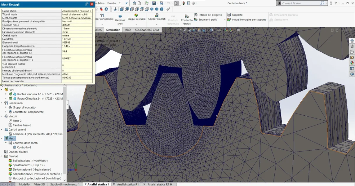
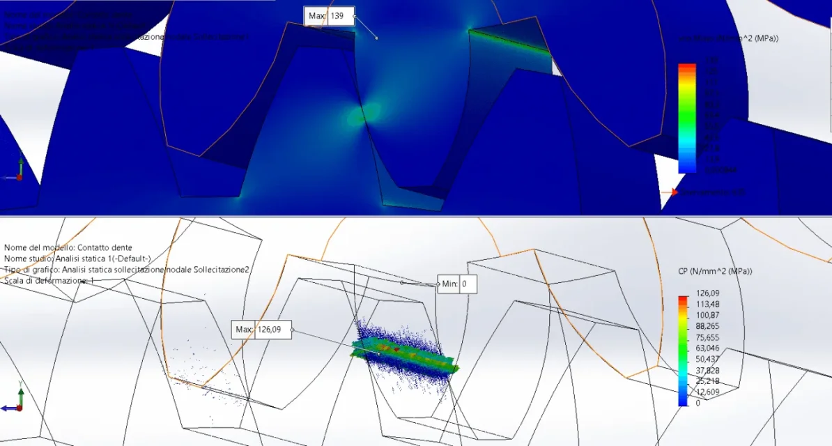
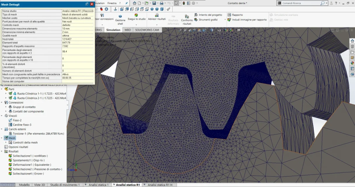
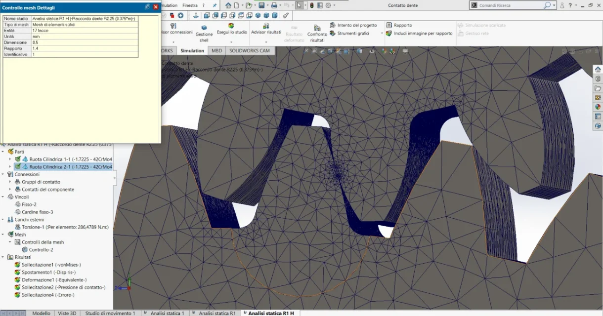
today I will smoke my pc a little, because I will again perform the fem simulations on the wheels, using everything I learned here to compare a little numbers. I will improve the mesh by inflating it even more on the tooth (I will make elements from 0.5mm as recommended), I will use the mesh based on curvature and change the base connection radius. I do not know whether or not to use the h-adactive or p-adactive method or either. I will give you proof and I will update you at least to share with you the results.
 
Hello, everyone. I'm going back here, posting the results of what my PC has been working this morning.
in order, I performed 3 types of analysis:
1) without fitting, automatic standard analysis without iterative methods [Analisi statica 1]2) tooth connected with r=0.375*m which in my case would be 2.25 mm (as recommended by mechanicalmg), standard analysis without iterations [Analisi statica R1]3) related tooth and analysis with h-adactive 4 iterations (it was the longest as 44 minutes processing but did not give the hoped results) [Analisi statica R1 H]for all three analyses I used a mesh based on curvature and applied a mesh control to inflate on the tooth (called mesh attachments)
results:
performing with the probe command an average voltage values on the tooth root, I find myself with values very close to those calculated by mechanicmg with the iso 6336 for the bending of the tooth (65.8 mpa vs 67mpa calcoalti; far away from my 81mpa calculated with the agma) only in case 1, in others (in which the connection is present) I find values about halved.
As for the contact pressure we are very far away. I don't understand what's wrong or wrong house.
other question, in case 3 if I show the mesh, known that it did not consider mesh control more dense, would you know why?
 

Attachments

  • Annotazione 2020-07-28 150514.webp
    Annotazione 2020-07-28 150514.webp
    198.4 KB · Views: 10
  • Annotazione 2020-07-28 150550.webp
    Annotazione 2020-07-28 150550.webp
    12.8 KB · Views: 9
  • Annotazione 2020-07-28 151118.webp
    Annotazione 2020-07-28 151118.webp
    25.6 KB · Views: 8
  • Contatto dente-Analisi statica 1-Immagine-1.webp
    Contatto dente-Analisi statica 1-Immagine-1.webp
    82.5 KB · Views: 8
  • Annotazione 2020-07-28 151253.webp
    Annotazione 2020-07-28 151253.webp
    208.9 KB · Views: 9
  • Annotazione 2020-07-28 151319.webp
    Annotazione 2020-07-28 151319.webp
    10.3 KB · Views: 6
  • Annotazione 2020-07-28 151635.webp
    Annotazione 2020-07-28 151635.webp
    24.3 KB · Views: 8
  • Contatto dente-Analisi statica R1-Immagine-2.webp
    Contatto dente-Analisi statica R1-Immagine-2.webp
    83 KB · Views: 8
I attach the last photos of the case 3
the details of the main mesh are the same as case 2, but I repeat it did not take mesh control more dense
 

Attachments

  • Annotazione 2020-07-28 153458.webp
    Annotazione 2020-07-28 153458.webp
    24.5 KB · Views: 7
  • Annotazione 2020-07-28 153702.webp
    Annotazione 2020-07-28 153702.webp
    143 KB · Views: 7
  • Contatto dente-Analisi statica R1 H-Immagine-1.webp
    Contatto dente-Analisi statica R1 H-Immagine-1.webp
    77.5 KB · Views: 7
Keep in mind that the agma values may differ from those of the iso/din norms precisely because of the coefficients used, roundings etc. in fact, it would be good to compare the methods of calculation between them as a final result and not in the individual voices, because surely the difference you find.

we have:
♪[ \epsilon_N=\frac{ga}{p} \] that is from the length of the action line divided the basic circular step. are a lot of formulas to get there and calculation of different parameters and angles.

regarding helical replenishment we have:
♪[ \epsilon_E=\frac{b•sen(\beta)}{\pi•m_N} \] that is the product between useful width gear band for the sense of the propeller angle, divided lazy multiplied the normal module.

the total cover is the sum of the two values.

I recommend you to delve into the niemann or a good book of gears.
 
Keep in mind that the agma values may differ from those of the iso/din norms precisely because of the coefficients used, roundings etc. in fact, it would be good to compare the methods of calculation between them as a final result and not in the individual voices, because surely the difference you find.
So if I just want to follow the Agma rule, how should I interpret the results of the analysis?
What if I want to compare the two rules?
we have:
♪[ \epsilon_N=\frac{ga}{p} \] that is from the length of the action line divided the basic circular step. are a lot of formulas to get there and calculation of different parameters and angles.

regarding helical replenishment we have:
♪[ \epsilon_E=\frac{b•sen(\beta)}{\pi•m_N} \] that is the product between useful width gear band for the sense of the propeller angle, divided lazy multiplied the normal module.

the total cover is the sum of the two values.

I recommend you to delve into the niemann or a good book of gears.
Okay, thank you very much. I will also deepen this aspect for personal culture, I do not know if I will also insert it in my treatment.

As soon as you are available and have time, I would like a judgement on the analyses carried out and how you would interpret them.
 
So if I just want to follow the Agma rule, how should I interpret the results of the analysis?
What if I want to compare the two rules?
Okay, thank you very much. I will also deepen this aspect for personal culture, I do not know if I will also insert it in my treatment.

As soon as you are available and have time, I would like a judgement on the analyses carried out and how you would interpret them.
for comparison between the two norms you will compare safety coefficients for pressure and bending. You can't do anything else.
if you have used the agma norm or try to remake the accounts and improve the reading of the curves or keep them as reference values.
 
As for the analysis, I can tell you that the iterative system is giving you good results. But the mesh must be finer.
I believe that the linear calculation cannot give better results. it would be necessary to try to do non-linear analysis, both for the type of application of the load and for what happens to the material.
I understand, thank you very much for the feedback.
So recapturing, the optimistic way is the one with the adaptive, mesh fit, but to have better results I have to try a non-linear analysis, right?
At this point, as that anlysis took me a long time, could I lighten the model by dividing the larger wheel in half and then set a symmetry bond?
tomorrow I try for this way, hoping to achieve the desired results, i.e. a root stress that approaches my results, and a much higher contact pressure.
Thanks again!
for comparison between the two norms you will compare safety coefficients for pressure and bending. You can't do anything else.
if you have used the agma norm or try to remake the accounts and improve the reading of the curves or keep them as reference values.
the values of the graphs I have interpolated them, even several times. so I can only have them as a reference, hoping to approach those values with non-linear analysis.
Do you have any advice or insights about nonlinear analysis to give me before I quit without understanding anything? ?
 
for non-linear analysis you need the simulation version higher than normal.... otherwise nothing to do.
then you must also set the material according to the sigma/epsilon curve.
 
Yes, I have the version that allows me to perform non-linear analysis.
then you must also set the material according to the sigma/epsilon curve.
I was aware of it, but for my material I did not find data on the net for the stress-deformation curve, how can I define it?
 
the curve you could build it or ask the laboratory of some universities if it provides you with the curve or data.
It is also true that you could make a bilinear hypothesis and then build from zero to yield the linear curve and then, knowing the total lengthening to break, make the second curve.
 
All right, very kind and helpful.
Now I have to see to put everything in order because, without noticing "I put so much meat on the fire" ?. if I can get the curve s-d well, otherwise I have to see how to do. for now I thank so much those who supported me, perhaps I give us two lines in the thanks of the thesis:d.
If I need more comparison, I'll show up.
 
Looking at at atlas of stress strain curves 2nd edition there are the curves of materials that approach yours.
you have a 42crmo4....and on the book there is 40nicrmo7 which is a slightly better alloy than 39crnimo3 which is a 42crmo4 replacement for gears and stressed pieces.
on the book you find it as sae 4340.
Screenshot_20200729_191304.jpgit is necessary to check well if there is a better curve or with different treatment because this is hardened and it is also good.
I found this for now.
It would be necessary to understand sae 4320 what is approaching.
 
I also found the atlas, but not being so hard on the sigles I didn't know which steel to make head. Let's say that once I have the chart, I collect the values by manually extracting them and insert them into solidworks.
calmly I will try to do everything, although today I did a nonlinear analysis of attempt, without inserting the s-d values (I left isotropic linear elastic). I certainly did wrong and I made the pc work out uselessly for 3 and a half hours, getting no "good" result, indeed worse results than static analysis. so the analysis not linear would use it as the last beach.
Anyway, as soon as I put everything in order, I'll be alive. Maybe if I can write in this tread, I'd discuss some trees. Otherwise I open another tread not to confuse things.
still so much gratitude for the time dedicated to me. ?
 

Forum statistics

Threads
44,997
Messages
339,767
Members
4
Latest member
ibt

Members online

No members online now.
Back
Top