yas
Guest
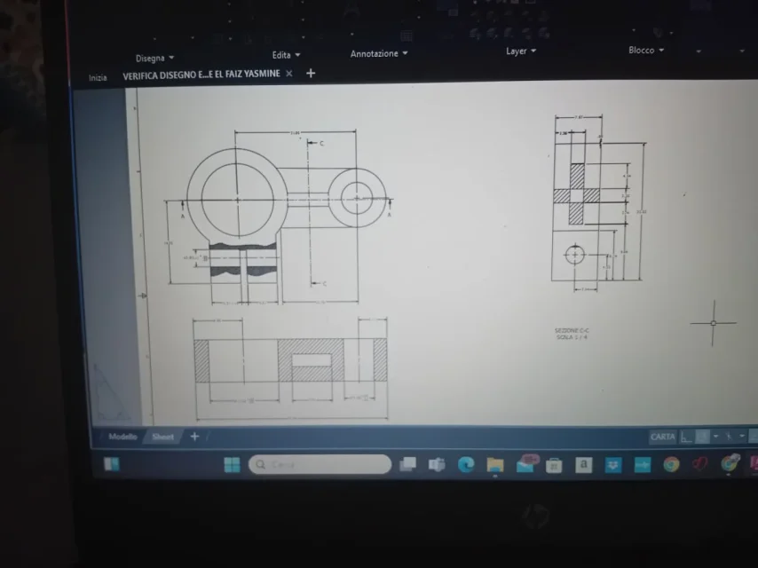
good morning to all,followed a itis high school, I made the table of a 3d and I do not know if I made the appropriate and useful views/sections including quotas.
I need help because I do so much work in drawing and I can't orient myself
Thank you very much
attached drawing 3d and table setting.
I need help because I do so much work in drawing and I can't orient myself
Thank you very much
attached drawing 3d and table setting.