• This forum is the machine-generated translation of www.cad3d.it/forum1 - the Italian design community. Several terms are not translated correctly.

extrusion advice: curiosity

  • Thread starter Thread starter volaff
  • Start date Start date
Good morning to all friends.
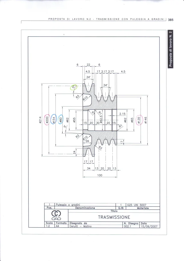
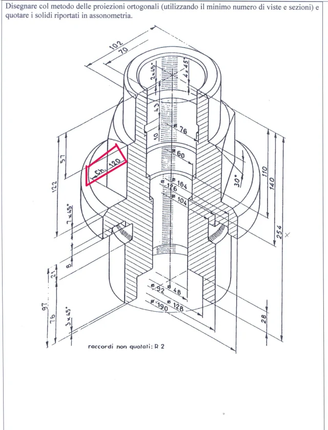
I wanted to take the road to model the following together ( fairly simple for now) of the pdf file.
for now I have part file notion and draft file.
piano piano piano I will also see the assembly part for which I already have video tutorials in English and well done ( understandable).

I modeled the pulley to steps but I can not understand what refers to that altitude of 5° on the top left (page3 of the pdf file) where there is the connection of 3 mm.
I had thought of a bevel, however, lacks information about "one side" of the bevel triangle.
I hope you will be able to satisfy my doubts, surely foolish.

in the pdf file there are almost all components except the protection rings and the greaser + the unified components.
Would you tell me where I can take the same to shape them or, if there are, already downloadable somewhere?

thanks to anyone who has had the patience and the desire to read this post.
Greetings.
fly
 

Attachments

Don't you see the scan is conical? the 5th is the inclination of the wall.
you will have an isoscele trapeze with base 37 (154-80/2) high 26 and with the inclined sides of 5°. It doesn't seem so hard! !
for protection rings find a bunch of catalogs. a great site is the trelleborg even if you have to do some hand to find what you need http://www.tss.trelleborg.com/globa.../detailpages_shaftseals/radial-oil-seals.html
su tracepart find it almost certainly
Mom, what a fool I am.
first I have to do the trapezoidal excavation and then the fitting: Who knows I believed.
In the evening, I'll do it again with a lot of food.
I also modeled the spacer rings and asked me something about the section: if I realize a section of a particular asymmetrical how can I keep the view in section and delete the main view that generated it?
Is that possible?

I tried with "interrupt alignment" but, of course, this allows me to move only the view; if I gate the priniciapale also deletes the section.

Thank you very much for your patience.

Good evening!
 
for that type of section you have two possibilities
mode 1: do the classic section and hide the main view by putting it out of the sheet because it doesn't bother you when you have to select the section. hidden view during printing or zoom extension is not considered
mode 2: Make a rectangle that understands all geometry and do a decomposed section by selecting as a parameter a provisional axis (of course you have the kindness to display them for this operation) in this way the section will arrive exactly at the center of your set or particular
 
I'm looking at the pulley now and I'm telling you what to fix
- the trapezoidal seats and belts are not well shaped like that. If you try to change angle 34° you will see that it does not maintain symmetry with axis or equality among others. this because you have given as parallel bonds between faces and middle points with axes. the constraints to give are quotas between the axes (which are those that command the position of the straps) and symmetry between the tilted walls and the respective axis. then from the parallelism between the walls on the same side (the other three obviously do not serve), probably will give error but you have put reunioning relationships and it is a mess to understand which is too much. I suggest you cancel those three excavations and give them back to you.

What I'm telling you now is my hub so do as you get better
the seeger seat of 2.15 I prefer to make it in a separate function rather than embedded in the hole for the following reasons:
-the seeger is an accessory element that can also be removed in the design phase preferring another type of locking and suspending a function is decidedly easier than changing a sketch
- there are library functions (task bread>design library >features>ring grooves) that automatically make them check that the measurements are correct
- if the size of the bearing is changed I tro more practical manage the size of the seeger seat apart without having to worry about the surrounding geometry
- if needed I can rename the function in order to identify it immediately among all those of the tree if it is a particular complex.
but these as said is my method that might not suit you, but I was trying to report it to you.

Good job
 
a hug seems exaggerated, a pat on the shoulder and a beer are more than enough or zero packages and two beers even better.. .
 
Good morning.
I tried to do the corrections you suggested to me and I think at least the part file managed well.
I had a couple of questions about the draft file.
I initially didn't know how to quote quotas in blue, then I thought I would also use the command that you suggested (virtual shape) and so I did: of course the text of the quota was without the fi of the diameter that I added in the text "hand".

I'd like to know if I did well or there was another way to solve this.

As for the quotas in red I was wondering if I must necessarily insert by hand the lines of half-carry from the sketch environment and then quote the same inserting in the text of the quota the fi of diameter.

as much as the inclination of 5° (green) I could quote it regarding the axis of the pulley without problems but the view would be quite weighted: Is there a way to quote it as done in the 2nd annex? ?
But I don't know whether it's right or not?

Thank you very much for your patience.
Have a good day.

:

ps: As for the views in the section of the spacer rings I simply clicked right in the draft shaft and pressed hide: at this point asks you if you want to hide even the views connected to the main one and choosing no remains only the view in the visible section.

I also attached the other case parts to anyone.
 

Attachments

a hug seems exaggerated, a pat on the shoulder and a beer are more than enough or zero packages and two beers even better.. .
As soon as I can attach the file and draft of the tree.
Maybe a silly question about the draft file.
if in the sketch of the part I used deglle lines of reference (type axes) it is possible to import them directly into the environment part or must I necessarily add of lines of half-carry (assi) " by hand " by sketch and then to quote the latter?

Greetings at the forum!
 
waiting for some advice and correction I also attach the part and draft of the tree.
Good Sunday to all.
 

Attachments

I just have to look for the unified parts to complete the axieme hoping that the masses in tables are decent.
Good weekend, everyone.
 
Hello, everyone. I tried on the net but I didn't find anything.
What is that red quota "ch.120"?

Thank you.
Good evening.
 

Attachments

  • immagine.webp
    immagine.webp
    296.1 KB · Views: 10
is the measurement of the hexagon key.
but still with 'st sketches of drawings... the forum is full of steps you can use to learn to shape
 
is the measurement of the hexagon key.
but still with 'st sketches of drawings... the forum is full of steps you can use to learn to shape
Thank you very much.
the problem is also to understand the old drawings and seals:)

should be the top-level distance of a regular hexagon therefore. Thank you.
 
No, no, no. is the extent to which the English key is inserted. if you look well at the drawing the quota is perpendicular to one of the sides
Obviously on google there is no image. see if I find something on one of the pdf bolts. . .
 
No, no, no. is the extent to which the English key is inserted. if you look well at the drawing the quota is perpendicular to one of the sides
Obviously on google there is no image. see if I find something on one of the pdf bolts. . .
Thank you very kind!
 

Forum statistics

Threads
44,997
Messages
339,767
Members
4
Latest member
ibt

Members online

No members online now.
Back
Top