• This forum is the machine-generated translation of www.cad3d.it/forum1 - the Italian design community. Several terms are not translated correctly.

fillet seal

  • Thread starter Thread starter Guido
  • Start date Start date

Guido

Guest
Hello everyone,

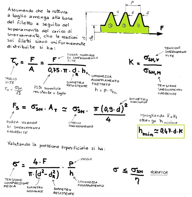
a gulf for lifting a load, screwed only for 3 laps that reduction of load has (if you have) regarding the entire screwing (axis load with the threaded pin) ?

Thank you.

guide
 
hi I drive, from what I know, from studies made with photo-elasticity, in the threaded organs almost all the load is erected exclusively by the first three threads in socket. Now from this consideration to say what is the reduction of the load I think is not simple.

Perhaps you can opt for a good safety coefficient, but consider that if the gulf is subjected to a minimum of bending, the conditions are more burdensome.

Obviously it depends on the operating condition, especially if there are operators around.

a greeting

simone
 
hi are violinox when you need to calculate a thread inserting a gulf into the threaded hole you must keep in mind the material where it is screwed. If the material is aluminum it is obvious that three threads are few, if the material is steel it is obvious that it will resist more. the rule is that in steel must be at least once the diameter while for soft metals like aluminum. brass etc. must have a length from once and a half the diameter to twice the diameter. but you must always calculate in the number of threads in the socket,calculating the section at the base of the thread for the number of threads in the socket. the unit stress varies according to the material, so be very careful because if it were to break or tear the threads in the socket you could cause dead.
 
really for steels we talk about half the diameter.
in fact the dice are slightly higher than half of their diameter.
for aluminum, brass, bronze, once and a half is right, but also two.

It always depends on the diameter, but three threads in socket, on the paper, should maintain. However if you tighten a bit stronger and deform a thread, you lost 33% of the load...I would avoid.
 
from the theory, by making the due approximations the length of coupling is calculated by rounding for excess according to the materials:
lmin >=0.47*d*k

con k = rsv/rsmvRSV: screw yielding load rsmv: Maternal yielding loadd: nominal diameter screwTheater: minimum mating length

this applies to threaded holes made with minimum hole tip and with males for h6, i.e. with 75% of useful surface of cutting resistance of the coupling crests/wall thread.
if the gulf has the long thread and can be screwed only for a few millimeters, I highly recommend the use of a spacer between the plan of support and the underhead of the gulf, so as to redistribute the forces also in shooting other than the vertical one.
This is beautiful... I think I've seen you around this forum, but I do.

so if the mothervite is softer, increase the fillets in hold, if instead it is softer the screw can shorten them?
However, if we talk about the same material, k=1, and we find more or less the half diameter.
 
if the gulf has the long thread and can be screwed only for a few millimeters, I highly recommend the use of a spacer between the plan of support and the underhead of the gulf, so as to redistribute the forces also in shooting different from the vertical one.
I feel like I quote the above because I consider it a good observation!


great forum, educational. :smile:
 
from the theory, by making the due approximations the length of coupling is calculated by rounding for excess according to the materials:
lmin >=0.47*d*k

con k = rsv/rsmvRSV: screw yielding load rsmv: Maternal yielding loadd: nominal diameter screwTheater: minimum mating length

this applies to threaded holes made with minimum hole tip and with males for h6, i.e. with 75% of useful surface of cutting resistance of the coupling crests/wall thread.
if the gulf has the long thread and can be screwed only for a few millimeters, I highly recommend the use of a spacer between the plan of support and the underhead of the gulf, so as to redistribute the forces also in shooting other than the vertical one.
quoto what said by mechanicsmg. I just wanted to add that that is a theoretical account as for unified dice is the report l=7/8 d.
 
this a bossard link with a computer to determine the required thread length for different materials.http://www.bossard.com/tools/thread_engagement_length/index.cfmthere is also a great complete manual on the unmounted connections:http://www.bossard.com/index.cfm?ap...mid=3075&app_fileid=7074&app_source=text_filein truth the speech to couple different materials should pull out stiffness and not only resistors.
For example if I switch a metal screw with a plastic screw, I can get to have a seal of the whole screw by making a thread in the very deep plastic. This is because the elastic plastic module is very low and compared to that of the screw and so the screw can put all the threads at once.

on the contrary by mating a metal screw with a rigid and fragile material, even if I make a high thread depth, risk that the first threads are damaged in the socket, which yielding the load to the next threads, etc. the mother screw never manages to hold the total load of the screw.

in reality, it has a plastic deformation of the first threads and a redistribution of the load to the successive threads. If the material is not really very fragile this redistribution does not lead to any problems whatsoever.

greetings
wave
 
Excuse me, is the mythical formula that proposed mechanicalmg located on the baldassini?
If you can tell me where I'm gonna sign it?
I didn't find her.
 
Excuse me, is the mythical formula that proposed mechanicalmg located on the baldassini?
If you can tell me where I'm gonna sign it?
I didn't find her.
pierarg is not on the baldassini... I got it a long time ago, since it's of interest, I put the procedure.
method for sizing mating length and verification at surface pressure of the coupling type.
 

Attachments

  • dimostra viti.webp
    dimostra viti.webp
    146.9 KB · Views: 987
thank you for the kindness
:finger:
Please! This, like most of my notes, is the fruit of sleepless nights, where I go hunting for truths trying to prove everything with a logical sense.

You know what it is... with the classic manuals I don't find myself, instead if I Synthetic in my notes I have photographic memory and above all an extreme speed of consultation and application, all on a single source.
 
very interesting, but you base yourself on the assumption that the load on the threads in socket is the same.
Actually, we know that's not true. So? is your account precautionary or not?

I don't have time to think about it, but I try to study your approach better, which seems well done.
 
very interesting, but you base yourself on the assumption that the load on the threads in socket is the same.
Actually, we know that's not true. So? is your account precautionary or not?

I don't have time to think about it, but I try to study your approach better, which seems well done.
Of course, I am based on the fact that the traction force (action/reaction screw/magnet) is uniform on each thread stroke for all threads in hold.

the precautionary value lies in the verification of the average compression voltage (last row, 2 formulas) with the safety factor.

However when you have time to think about it, we can develop it and perfect it:wink:
 
in this old discussion:http://www.cad3d.it/forum1/showthread.php?t=18891I posted the pages of the malavasi that treat the verification of the length of the threaded connection (and it is shown that the bending verification is more severe than the cutting one).
we always talk about complete threads, in a unified screw the initial part is conical for a length pairs to a maximum of two times the step, so if I screw the gulf for three threads I have to consider suremnete in taking only one, and the verification, to go on the safe, it is to be done on that only thread.
Hello, everyone.
 
Good morning, gentlemen, I take this discussion because I have had a similar problem.

a customer introduced me two aluminum pieces connected by a threaded grain m10.
a piece (full worked aluminum) has a blind threaded hole m10.
the other (aluminum die-cast) has a passing hole.
grain (steel) screws on the blind hole and then tightens with a steel nut.

the questions are two:
- for the connection length of the blind hole I would simply follow the recline equal to at least 1.5 times the diameter (perfected by the brilliant demonstration of mechanicsmg)

- The strange question I asked myself is this: "Why did you use a threaded grain?"
I would have used a posonist. generally use the grains to fix/block.

Can you enlighten me?
Thank you.

p.s: I have no way to post a link pattern however is the classic piece1+piece2 link with piece1 (pass hole) and piece2 (threaded blind hole)
 
always to throw it there that I don't have time... but 10011 sucks you as an approach to threaded collection? ! ?

p.s. the 3 laps refers to the 3 laps of the screw and not to the threads in the right grip?so it should be evaluated, knowing the step, how many threads in the grip there are...
 
the questions are two:
- for the connection length of the blind hole I would simply follow the recline equal to at least 1.5 times the diameter (perfected by the brilliant demonstration of mechanicsmg)

- The strange question I asked myself is this: "Why did you use a threaded grain?"
I would have used a posonist. generally use the grains to fix/block.

Can you enlighten me?
Thank you.

p.s: I have no way to post a link pattern however is the classic piece1+piece2 link with piece1 (pass hole) and piece2 (threaded blind hole)
with certain fairly short dimensions it is preferable to use a grain than a prisoner. the prisoners are partially threaded and cost more and not all keep them available in stock, while the grains are located everywhere and to tighten them is enough a brugola key (which the prisoners do not have).

probably if the customer makes an automatic assembly it is very convenient to feed/select/slide/slide a grain compared to a prisoner.

for the profodity attached to that by law and verify it with my vormula depending on the characteristics of the materials.
 

Forum statistics

Threads
44,997
Messages
339,767
Members
4
Latest member
ibt

Members online

No members online now.
Back
Top