• This forum is the machine-generated translation of www.cad3d.it/forum1 - the Italian design community. Several terms are not translated correctly.

interpretation

  • Thread starter Thread starter volaff
  • Start date Start date

volaff

Guest
Hello, everyone.
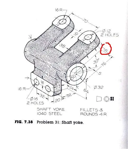
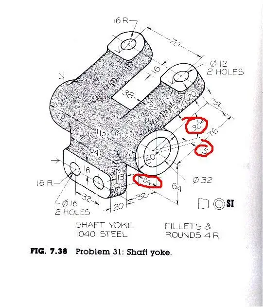
I should model the piece that I attached but I did not understand the sense of the odds circled in red (I also cerchaito the angle quota of 30° but only for completeness).

the quotas of 24 and 5 are to indicate that the circumference of diameter 50 is not straight, but tilted jurist?
or did I misrepresent things?

night to all!
 

Attachments

  • Disegno0901.webp
    Disegno0901.webp
    56.4 KB · Views: 112
Hello, everyone.
I should model the piece that I attached but I did not understand the sense of the odds circled in red (I also cerchaito the angle quota of 30° but only for completeness).
24 is the distance of the lower support (the one with the two holes) from the extremes of the central cylindrical body.
5 is the recess from the extreme of the central cylindrical body of the inclined support: 112-38-32-32/2 or(112-70-32)/2
the quotas of 24 and 5 are to indicate that the circumference of diameter 50 is not straight, but tilted jurist?
or did I misrepresent things?
The second you said...

Would you send me references to the author of those drawings? I want to insult someone today. In the absence of any other, your professor's e-mail:
 
I press that this design found it among old things of unviersity: I don't even remember who gave it to me! ! !

I think that doing it with olidworks for me will be a nice crush on the front then! !

Thank you very much for the tips!
 
...
Would you send me references to the author of those drawings? I want to insult someone today. In the absence of any other, your professor's e-mail:
or you could walk on it with the crushers:biggrin:
 
to make this piece cmq I think it agrees to start from the base with the two holes.
As soon as I pass this irritation to my eye I draw.

thank you all for the attention!
 
to make this piece cmq I think it agrees to start from the base with the two holes.
As soon as I pass this irritation to my eye I draw.

thank you all for the attention!
look that however the piece is not complicated, indeed, are 3 parallelepipeds and a cylinder.

I would start from the cylinder because in this way I have the axis that makes me reference for the vertical planes (for the base) and the plane of 30° for the two brackets.
 
And here's my work of art....ah ah...

How do you look? ? ?
ps: I did not understand the meaning of the quota in red so I did the piece without using it (at least implicitly) :-)
 

Attachments

  • Part1.rar
    Part1.rar
    274.2 KB · Views: 7
  • Disegno09011.webp
    Disegno09011.webp
    55.5 KB · Views: 58
the 32 circled quota is the distance between the surface with the ø12 hole and the cylinder axis ø50.
you made a small mistake: the sketch4 must be tangent to the cylinder ø50 and you must eliminate the bond of truthfulness with the origin.
 
ok modification carried out.
that share of 32 at the end I find it by adding the other quotas I used to define the model.

If there's only one mistake, I'm a monster..auhauhauh.

Thank you very much for correction!
 
I don't understand why you keep "taking" with these old drawings. I find them very simple, exhausting and completely quoted (in a playful way limited by the asonometry). for those with the first weapons, with the first notions of technical design (and perhaps only that, not yet tolerances, neither technology, nor construction), must obtain the correct orthogonal projections. I repeat I was doing the same 32 years ago when I was 15 years old. the texts were filled with similar assonometry, surely dating back to the period between the two wars:smile:. they do not want to be examples of the "state of art" of representations perfectly according to norm (but for a hypothetical simple workshop of the time they were still completely edible); I see them more like a hand sketch "in 3d", quoted quickly (even badly maybe) but exhaustively. of course everything is then to put in the table correctly; and this will be the task of the student.
 
Last edited:
I don't understand why you keep "taking" with these old drawings. I find them very simple, exhausting and completely quoted (in a playful way limited by the asonometry). for those with the first weapons, with the first notions of technical design (and perhaps only that, not yet tolerances, neither technology, nor construction), must obtain the correct orthogonal projections. I repeat I was doing the same 32 years ago when I was 15 years old. the texts were filled with similar assonometry, surely dating back to the period between the two wars:smile:. they do not want to be examples of the "state of art" of representations perfectly according to norm (but for a hypothetical simple workshop of the time they were still completely edible); I see them more like a hand sketch "in 3d", quoted quickly but exhaustively. of course everything is then to put in the table correctly; and this will be the task of the student.
what you say is correct, but, personally, too many "lines" give me to the head:-)
 
what you say is correct, but, personally, too many "lines" give me to the head:-)
the design of an object quasiase you must first have in the head... Then you draw it.
said this, stores the geometry of the model and then tries to put it on
computer or paper.
 
..that then, referred to the title of the thread, there is nothing to interpret. . just follow the quota lines. and if I see him that I am blinded as a mole.:biggrin:
 
I don't understand why you keep "taking" with these old drawings.
(cut)
serve for those with first weapons, with the first notions of technical design
I think it's the opposite. are for those who already have the eye to the reading of drawings quoted in assonometry, with lines of construction that seem to wander in space and "optimal" assonometric effects sometimes questionable or even wrong.
You read them on the fly (and then you have to look at us well...) that are sixty years old:tongue: that you mastichi, so you seem to have to understand them on the fly even the nests. :wink:
then put us that often lack odds and the frittata is made
 
I don't understand why you keep "taking" with these old drawings. I find them very simple, exhausting and completely quoted (in a playful way limited by the asonometry). for those with the first weapons, with the first notions of technical design (and perhaps only that, not yet tolerances, neither technology, nor construction), must obtain the correct orthogonal projections. I repeat I was doing the same 32 years ago when I was 15 years old. the texts were filled with similar assonometry, surely dating back to the period between the two wars:smile:. they do not want to be examples of the "state of art" of representations perfectly according to norm (but for a hypothetical simple workshop of the time they were still completely edible); I see them more like a hand sketch "in 3d", quoted quickly (even badly maybe) but exhaustively. of course everything is then to put in the table correctly; and this will be the task of the student.
Hi, sampom,
the speech you make is correct partly because this design is not so complicated. ... he still tries to see him with the eyes of a student who can't keep the team in his hand because he still has to learn. :finger:

there are some (see other recent threads) that are quoted so as to create confusion (if intended for educational use).
 
I think I said I was doing it at 15. of course at first with the slightest difficulties of any student (and not university..), but understood the game then spun sent. At least, I found them easy already then. . In fact, I liked to solve them. :biggrin:
 
I think I said I was doing it at 15. of course at first with the slightest difficulties of any student (and not university..), but understood the game then spun sent. At least, I found them easy already then. . In fact, I liked to solve them. :biggrin:
Let me insist. . :tongue:
it would be like to find interesting the use of a cad full of limits, to have fun to echo workarounds, or prefer a cad 2d to split the brain to control the correct execution of a section.
I have a design must always be correct, readable and without doubt on the interpretation of quotas.
if then the use is the didactic one to take out three views 2d and a section from a listed isometric view or vice versa little matter.
You don't need anything to learn how to read a bad design, that you can do it when you can read the good things, while the opposite is not that it's obvious, indeed...
 
I also agree with this.
I am not and I will never be a top to interpret the quotas (it will be because the drawing exam since the trianal I took it on....groppone) however....

for example in this case the quotas 30 and 40 refer to points a and b of the upper view or wrong?

ps: I have to make the repetition of the circled element in red but I can't totally define the profile, as I know the distance from the center (i.e. 108/2) and I know that the two tangent "races" to the arc must be symmetrical but I always have a missing quota (at least I think).

Good day to all

ps: I forgot something.. Many say that the tables that "play" have always been the same for years..mica is there someone who could send me just 3/4 so as to practice even more? ?

thank you all for the attention!
 

Attachments

  • lastscan.webp
    lastscan.webp
    136.8 KB · Views: 14
  • lastscan001.webp
    lastscan001.webp
    139.1 KB · Views: 18

Forum statistics

Threads
44,997
Messages
339,767
Members
4
Latest member
ibt

Members online

No members online now.
Back
Top