• This forum is the machine-generated translation of www.cad3d.it/forum1 - the Italian design community. Several terms are not translated correctly.

interpretation

  • Thread starter Thread starter volaff
  • Start date Start date
I understand the antiphon, maybe I'm not too "able," I admit.

you are able to do more than I can imagine, among these, for now, the drawing does not come back
in your best abilities.
They taught me... that all you learn, the limit is the time that each one of us takes to understand. . .
Get up!
 
you see it perfectly as you: the design does not fall into my skills (not by chance is the last exam), maybe I am better with equations.

that is why you are my salvation (and not only for drawing).

:-)
 
instead I interpret it in this way, the quota 19 for me is not referred to the end of the r41, welcome to the bevel of 30°.:wink:
 

Attachments

instead I interpret it in this way, the quota 19 for me is not referred to the end of the r41, welcome to the bevel of 30°.:wink:
I repeat my version, also in your model the 10 mm quota (evidenced with 5) is not there.
 
Hello mike 1967
the quota nr.5 is wrong of departure on the "original" design, really is 13.
he who has quoted this quota has made a mistake by quoting along the assonometric and non-real lines.:
 
instead I interpret it in this way, the quota 19 for me is not referred to the end of the r41, welcome to the bevel of 30°.:wink:
I repeat my version
I raise and see!

imho is right mauri because r41 is completely defined by the 10 mm quota of the tangent straight tract. I don't open the models, but if you put the quota 19 at the end of the arc r41, there's some other quota for sure.

p.s. these last posts are proof that these designs are unclean cows that can complicate life even to those who are navigated. I add that I'm sure that if you get to the workshop a piece designed and quoted to that way they would want the keys of the 40 towards the u. Look only how the arc of the quota is made at 30 °, or better where is its center... Even a drunk would do so
when you are fasting of matter you do not need anything to learn about wrong teaching materials. It's a useless waste of neurons, a source of inaccuracies and propable future aversion to technical design.
 
if even some of you have found "inconsistencies" this can only make me "happy." thank you very much always for the availability!
 
Please, but I want you to know that personally I care about... Since these are basic texts for those who will have to start, hopefully with the right foot.:frown:
 
I know though if the author is a little "confusionary" students can't do anything I know. :-)
 
Hello everyone again.
as usual I do not find myself in the value of a quota.
Would someone explain to me the meaning of the stake circled in red?

I think it is the vercidal distance between the hole axis (45 degrees compared to the horizontal) and the surface in grey.

in fact line 1 then is not parallel to line 2.

Have a good day!
 

Attachments

  • Schizzo.rar
    Schizzo.rar
    31.7 KB · Views: 2
  • lastscan.webp
    lastscan.webp
    443.3 KB · Views: 12
  • lastscan1.webp
    lastscan1.webp
    444.2 KB · Views: 10
  • lastscan2.webp
    lastscan2.webp
    441.4 KB · Views: 7
thanks mike1967 I had thought about this solution too.
the problem is that, now, the profile is not completely defined as there is that segment in blue not listed (which happens to me too). I don't know. :-)
 
thanks mike1967 I had thought about this solution too.
the problem is that, now, the profile is not completely defined as there is that segment in blue not listed (which happens to me too). I don't know. :-)
place the correct version complete with rays:
 

Attachments

  • 6.webp
    6.webp
    99.8 KB · Views: 7
Thank you very much after I try to remake and see if I find myself with your sketch.
Thank you so much!
 
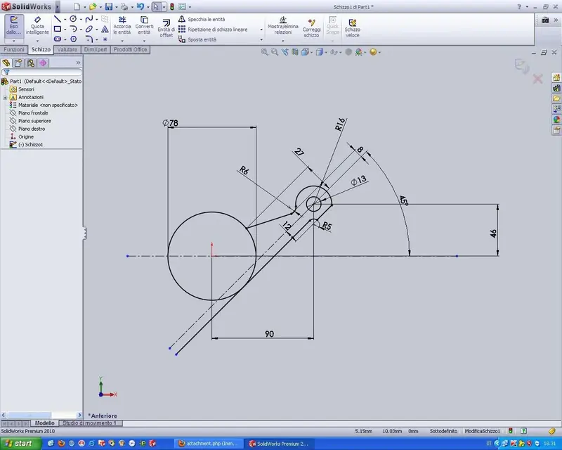
That's what I did.

In fact I couldn't completely bind the radius of 5 mm then I set a alignment condition between this radius and that of the hole of diameter 13.

hot comments?

Thank you all!
 

Attachments

  • Immagine.webp
    Immagine.webp
    71.1 KB · Views: 9
That's what I did.

In fact I couldn't completely bind the radius of 5 mm then I set a alignment condition between this radius and that of the hole of diameter 13.

hot comments?

Thank you all!
I was based on the indications in the drawing: the r5 share has the center on the vertical of the main eyelet.
 

Attachments

  • lastscan.webp
    lastscan.webp
    444.6 KB · Views: 5
But why do you do so complex sketches?
regardless of the used cad, I much prefer to use simple sketches and then perform successive cuts and rounds.
try to manage very articulated sketches, in case of change, can be really "fast".
 
But why do you do so complex sketches?
regardless of the used cad, I much prefer to use simple sketches and then perform successive cuts and rounds.
try to manage very articulated sketches, in case of change, can be really "fast".
I too (see post #52), but it is difficult to explain the "finished" object without those fittings.
Then every drawing is to itself: in my work, for example, where 99% of the figures are laser cut or water cut, I prefer to insert as many features as possible in the sketch to avoid unpleasant and expensive forgetfulness (means that I forget a 20x20 dime on a 20 mm thickness). .
 
in this case the basic feature is relatively simple: just extrude to the intermediate plane and labor of symmetry.

Thank you all for your help!
 

Forum statistics

Threads
44,997
Messages
339,767
Members
4
Latest member
ibt

Members online

No members online now.
Back
Top