• This forum is the machine-generated translation of www.cad3d.it/forum1 - the Italian design community. Several terms are not translated correctly.

sizing tubes ventures

  • Thread starter Thread starter mambo1988
  • Start date Start date
the values that come out to me are:
speed = 270 m/s approx.

I started from the qm=0,0012 kg/s knowing the rho= 3,13 kg/m^3 I find qv=0,003 m^3/s so I have v1=8 m/s about.... .
I said this I imposed bernuolli and convervation of the mass...
I arrive at the result by imposing pressure in the throat section of 0.8 bar(in my calculations I considered the venturi output at a pressure of 1 atm) a speed of about 270 m/s

I don't care about the dosage anymore, the important thing is that the venturi tube can suck, then with a faucet it all hurts!
in the data you wrote me ro=0,004:confused:

the dosage you need to make the starting assumptions: otherwise the problem remains indefinite and you can never solve it.

I will start from a dosage to 7%
si the detergent is liquid, it has a density about-equal to that of water therefore 1kg/dm^3
That's right. It's usually about water.


for the valve I mean one of the kind (page 20)
http://www.lavalvotecnica.it/italiano/gestra.pdf... opens to a few millibars (very low load loss).
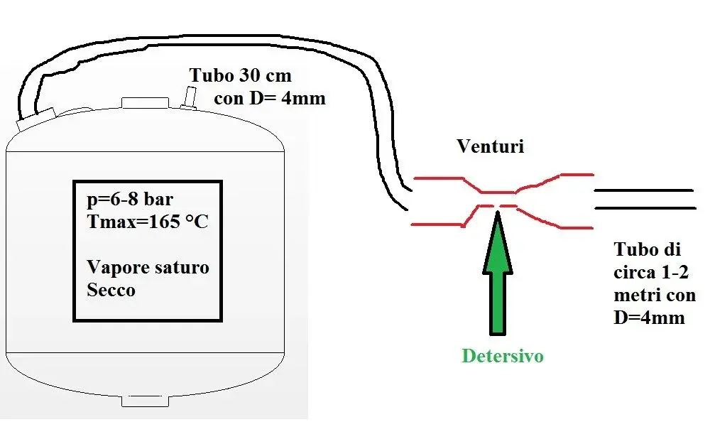
 
In fact it would not be bad to have a pattern of the whole circuit, with the sections and lengths and all the components (valves, gearboxes, etc.) present. .
 
this afternoon I realize it...for informational reasons I tell you:
1) steam comes out of a boiler( Static pressure 6-8 bar max, and tmax=165) through a hole of 1/8"
2) steam passes through a solenoid valve, and then passes into a piece of rubber tube (diameter 4 mm as the lower venturi) (for a max length of 30 cm)
3)steam enters the venturi tube(p1=2-3 bar pressure "dynamic", input section 1/4"(8mm), v1=8 m/s)
4)a valley of the "venturi" there is a rubber tube(4 mm) of about 1-2 meters

later I will make a sketch to make you understand better, thanks to all for the availability shown.
 
In fact it would not be bad to have a pattern of the whole circuit, with the sections and lengths and all the components (valves, gearboxes, etc.) present. .
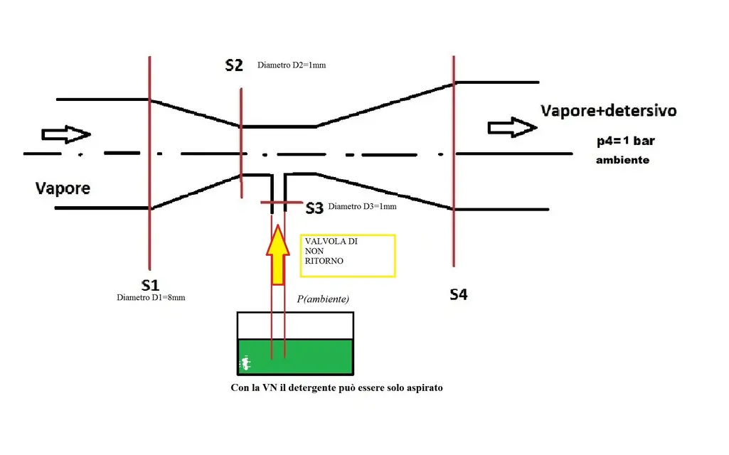
Here's a little rough pattern. . .

also in particular I attach the venturi tube for how it was dimensioned


p.s as you see from the design of the "venturi" section 4 is not pressure 1 atm...because then there is the rubber tube of about 2 meters

p.s1 hope you understand the problem from the box:smile:
 

Attachments

  • schemaaa.webp
    schemaaa.webp
    29 KB · Views: 13
  • TuboDet1.webp
    TuboDet1.webp
    50.4 KB · Views: 17
Here's a little rough pattern. . .

also in particular I attach the venturi tube for how it was dimensioned


p.s as you see from the design of the "venturi" section 4 is not pressure 1 atm...because then there is the rubber tube of about 2 meters

p.s1 hope you understand the problem from the box:smile:
I doubt that the tube has the same pressure as the boiler.
Do you have a way to put a pressure gauge at the venturi entrance?

p.s: I'm writing secretly from cell (otherwise my girlfriend asks for "divorce"). ..unfortunately I haven't done the calculations yet.
 
I doubt that the tube has the same pressure as the boiler.
Do you have a way to put a pressure gauge at the venturi entrance?

p.s: I'm writing secretly from cell (otherwise my girlfriend asks for "divorce"). ..unfortunately I haven't done the calculations yet.
ahh:biggrin: sisis in fact I put a pressure gauge, and I saw that during the operation the pressure drops to about 2.5 bar and remains constant....
 
ahh:biggrin: sisis in fact I put a pressure gauge, and I saw that during the operation the pressure drops to about 2.5 bar and remains constant....
indicates on the previous scheme where you put the pressure gauge.
do you also have a way to measure the flow?
 
indicates on the previous scheme where you put the pressure gauge.
do you also have a way to measure the flow?
at the exit from the boiler, there is a pressure gauge (say that it is placed between boiler and rubber tube of about 30 cm)....when the valve is operated, the pressure drops from 6-7 bar, to about 2.5 bar, and there remains constantly, so I measured the input pressure of the venturi!
 
I show you a fugitive example of venturi followed by a tube....
View attachment 28249in this example (which exists in all cars and which you can buy for a few euros in any bricolage shop), the fluid is aspirated and ejected after a brush of almost one meter of rigid tube.. .
In fact the aspiration takes place directly at the tip of the spear thanks to the depression formed in the nozzle, a few mm before the exit and that recalls the fluid from the sebatory. are two independent concentric tubes, the central one for the air and the outer one for the fluid aspirated by the sebatorium.
If you skip the terminal part of the lance, the one that allows the regulation of the amplitude and flow of the jet, you will see how it is done.
 
Yeah, you're right.
yesterday that I disassembled it I verified that it is actually done as you say.
I went to memory, but because of age I got screwed!
 
Here's a little rough pattern. . .

also in particular I attach the venturi tube for how it was dimensioned


p.s as you see from the design of the "venturi" section 4 is not pressure 1 atm...because then there is the rubber tube of about 2 meters

p.s1 hope you understand the problem from the box:smile:
Do you have a ø4mm tube out of the boiler that becomes ø8mm at the venturi entrance?
at the venturi exit the rubber tube continues for 1m or 2m?
 
was made especially for difficulties in the realization of the piece,
Moreover, the gas metric is not standardized with regard to the internal diameter (i.e. fittings, consisting of 1/8" with different internal diameters)
Considering for a 1/8" tube has an internal diameter of 6 mm (then it changes especially in this field, if you have to deal with high or low pressure.

I think that this does not affect the dimensioning i.e. if the mass flow is constant, changing section varies the speed and therefore input conditions... .
yes the fittings, section changes, etc... will cause load losses, the problem that I have is that I can not dimensional the venturi with the downstream tube.

for the sizing I used bernoulli and the mass preservation between venturi input and restricted section (where I imposed a lower pressure than atmospheric pressure) so I found my restricted section.
 
boys at the end I think I have solved, the solutions are 2:
- I put pressure on the detergent tank (poor practical)
- put the detergent container over the venturi at a certain height (very simpler)
 
boys at the end I think I have solved, the solutions are 2:
- I put pressure on the detergent tank (poor practical)
- put the detergent container over the venturi at a certain height (very simpler)
neither of them....the first one is improposable.
If we define the input data well we can do a venturi as you must.

your problem is not the venturi but the difinition of the input data.
 
neither of them....the first one is improposable.
If we define the input data well we can do a venturi as you must.

your problem is not the venturi but the difinition of the input data.
but the data I have all... Today I spoke to a professor of fluid mechanics who pointed out to me that in the valley of the venturi I have a pressure that is greater than the atmospheric one or 1+x, due to the load losses in the rubber tube, as the detergent is p=1 atm, this makes the aspiration no longer happen.
to have a pressure that wins these localized and distributed load losses or puts a pressure tank(but it is not convenient) or by varying the washing height of the detergent so as to have a greater pressure (today I tried it in garage and actually works)....
the problem now is to calculate the minimum height to place the tank.

What do you say? ?
 

Forum statistics

Threads
44,997
Messages
339,767
Members
4
Latest member
ibt

Members online

No members online now.
Back
Top