• This forum is the machine-generated translation of www.cad3d.it/forum1 - the Italian design community. Several terms are not translated correctly.

together welded and analysis fem - inventor 2017

  • Thread starter Thread starter vale79
  • Start date Start date
of course the load goes to affect all components.
But you could analyze the wall attack and see if it resists, then switch to the bar and do the same.
In this way you can optimize the components in a simpler way.
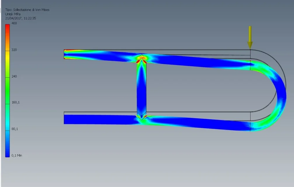
Why do you think with the new load the result is not okay? I see a high voltage value in the color bar, but in the piece I do not see red areas.
Maybe you have an incorrect concentration at one point. It also checks well the mesh which is very important.
If in the area where you have concentration of tensions mesh is irregular the cause could be that.
 
the highest value of the scale is 1142 mpa on the plate and 1350 mpa on the bar. these values are much higher than the 355 mpa of the module of young... If I scaled everything with 355 scale bottom (considering that the safety factor is already included in the load) I would feel red...
 
This seems to me realistic.
I had to remove all the accessories too much because even suppressing them continued to mesharli and messed up.
so it seems good, and above all the result is ok, what confirmed by real evidence.
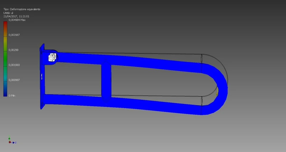
What I do not understand now is the unity of deformation, puts it in linear unity but the thing for me has no meaning, I cannot understand it.
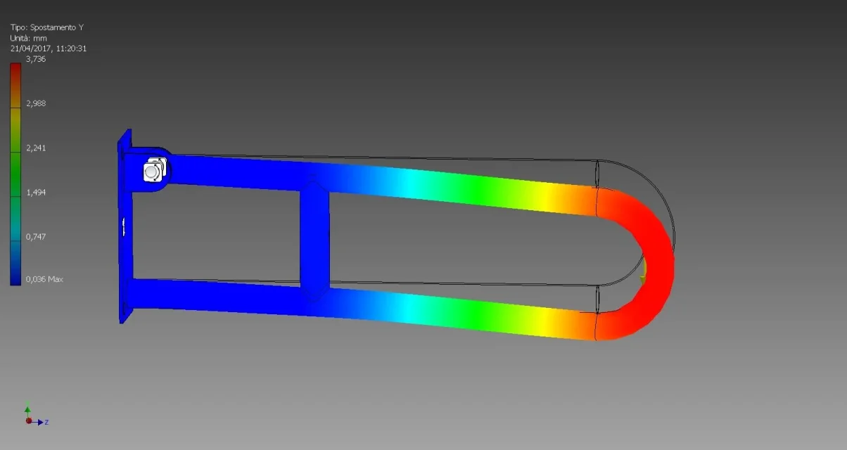
In deformation I would expect what I see instead of moving.
or all this means that at the end of all the test there will be no deformation but the move of 3 mm that I see will return back in the field of elastic deformations, what consistent with the fact that we do not exceed the module of young?
 

Attachments

  • 640-I_rest_sald_pulita.webp
    640-I_rest_sald_pulita.webp
    33.8 KB · Views: 4
  • 640-I_rest_sald_pulita_def.webp
    640-I_rest_sald_pulita_def.webp
    27.7 KB · Views: 5
  • 640-I_rest_sald_pulita_spost.webp
    640-I_rest_sald_pulita_spost.webp
    27.6 KB · Views: 5
Why the Young Form?
do you not consider the resistance to yielding for calculation?

I made a small test very fast to take with the springs as I do not know measures, material etc.
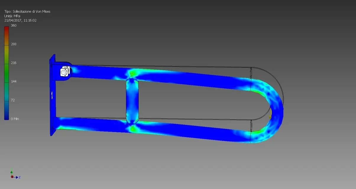
this the resultFEM maniglia.webpI have as maximum value von mises of 840 mpa.
But if I look at the color scale with a 400 setting, lower than the stress to yield the material I have inserted, I see that it is only elevated in small areas. probably this is due to how I shaped the piece that one part.
I don't see it so far from reality, obviously it has to be done with the right info and validated with experimental evidence.
 
Yes excuse me, 360 mpa is the resistance to the yielding of carbon steel (approximately) not the module of young.
and casually the bottom scale of my image was just 360, I didn't set it, so it seems quite realistic, as in reality the piece does not get ripped.
this also comes back with your image even if you have much higher values, but it is with the fact that the pieces are drawn differently.
the thing where I know a lot of difference instead is the low terminal of the bar, mine seems to not suffer stresses while your looks moved down. Perhaps it is due to the constraints or perhaps to what we said before on the armor, your piece is symmetrical while mine has the lower part shorter than the upper part (maybe you don't notice well with the whole bar assembled).
 
I have bound the high part with a fastening bond, the low with a frictionless bond.
this because below is only leaned and free to flow on the plane.
looking at your images seems to be bound by a fastening even below, or in any case with a bond that prevents it from sliding on the plane as it actually happens in your application.

another thing that, in my opinion, you have to do is characterize the material well. Maybe you create a custom.
It's important for the analysis, you have to put exactly the values of the material you use to produce the piece.
carbon steel values already present in the inventor's library are unrealistic.
even a simple e360 has higher values for example.
 
in the last image I posted there were no constraints in the bottom part of the tube, I fixed the plate and put some rotation constraints on the holes of the fins and the bar. and this comes back to me, compared to the real evidence, that with a fixed bond on the top the part under tent to open while with the rotation constraint do not. In my opinion, if I put a higher load in my simulation, it would tend to open up by taking the form of an a rather than an u.

Also regarding the material you have very reasonable, I have the certificates of the material of the pipe and I can take the data from these.
 
I can help you very little.
from what I know you have to turn the axieme, in your case are 2, that of the curved bar and that of the plate, in a welded assembly.
in this go insert the welds with the characteristics you need.
I hoped that inventor, once found a welded assembly, would automatically consider all its parts bound to each other.
If you take for granted that welds hold, can it be a viable shortcut to join all parts in one?
Otherwise if one finds a set already made in step how it must behave with inventor?
transform it into welded together, add all welds, put constraints and do analysis?
thanks for the attention and answers
 
Hello kaji
In my opinion, but I talk to you more about hypotheses than by experience, inventor considers the axieme welded just for what it is, that is, a set made of parts with different characteristics and gives you the optimal result.
If you are sure that welds hold, or you have complex pieces and want to check some parts separately, you can simplify the parts not relevant for analysis in unique pieces. For example I could have divided the analysis of plate and bar, wanting the analysis on the sole plate I could have considered the bar as a single piece not welded. here were only 2 simple pieces but perhaps in more complex analysis it comes useful.

I've never tried with a step, I don't know if it keeps the constraints or not.
 

Forum statistics

Threads
44,997
Messages
339,767
Members
4
Latest member
ibt

Members online

No members online now.
Back
Top