• This forum is the machine-generated translation of www.cad3d.it/forum1 - the Italian design community. Several terms are not translated correctly.

extrusion advice: curiosity

  • Thread starter Thread starter volaff
  • Start date Start date
for me the 70 is the height of the upper mozzetto; How does a share like that define a radius?
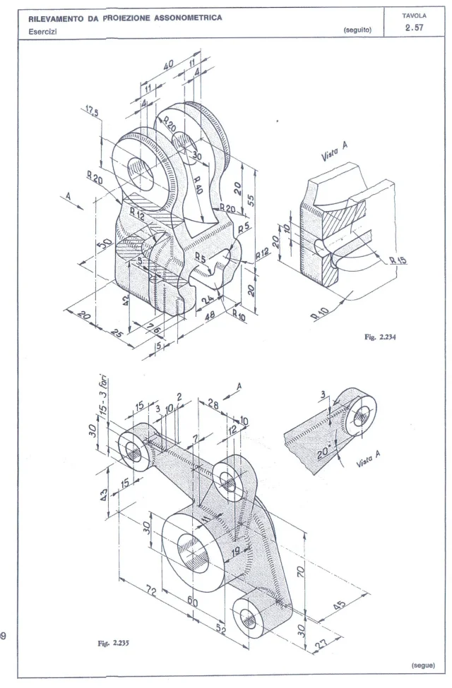
You're right! I was wrong with some turn right or left at the crossroads of who knows which line:redface:
the quota of the horizontal blue tract is derived from the view to where it indicates that it is 3 mm below the top extreme of the mozzetto (I learned a new definition) the arc tract is tangent to the blue and concentric line to the big hub and the inclined tract is obtained therefore going to place it tangent to the mozzetto on the lower right.

I miss the sense of drawings quoted in this way. What are they for? maybe to make sure that the new levers learn to share in the following penis? to accustom them to possible quoted designs to segugio penis?
I would like to see the scene in the workshop in case a drawing like this comes:
 
However, there are some fundamental quotas in addition to the view that allows us to understand how the rib behaves at the bottom of the central hub.
I learned a new definition
admit that you feel better now. . .
the art of creating random neologisms is strong in me
 
for me the 70 is the height of the upper mozzetto; How does a share like that define a radius?
Thank you both.
Marcof excuses if I didn't answer earlier but only now I saw your message.
on another machine I have the 2016 version of solidworks so I will open it with that file.

As soon as I can read all your notes calmly.
Sometimes I go in a hurry and I miss the info on the street.

in my file I used three profiles and 4 3d guide curves: as suggested by boulders the intermediate profile was created only to facilitate the construction of the driving curves, the profiles to be used were only two.
I read the rush post and I completely forgot this.

the proposed tables are of the volume "mechanical drawing" of manfè, pozza, discarded and I took them to practice with the software I used in the past.

many have suggested me catia but I much prefer solidworks: we hope in a better working future, while I am at home and among the various commissions I try to "study" again.

I thank you again for the support and, above all, for the time!
 
Thanks for the help only now I saw your answer to the post.
I thanked you in the post before this: I did double "quote" but it didn't go!
I'm glad to give you a hand and I think it's worth the same thing for rocks. You don't need to thank each time, unless you're trying to make up for all the times that the tens of your fellow students haven't done it in the past:
 
I tried to model but a turnkey comes.
If I try to shape the body to and then the body b and then I want to create the connecting body (blue) comes out a mess.
and the horizontal stretch in blue is tilted to me.
In fact, at least odds, the axes of the bodies a and b are distant 43 n vertical and horizontal
 
I'm glad to give you a hand and I think it's worth the same thing for rocks. You don't need to thank each time, unless you're trying to make up for all the times that the tens of your fellow students haven't done it in the past:
here is the result of the modeling.
How do I bind the 70 high mozzetto? ? ? ?

Thanks, guys.
to model it I placed on a floor 19 away from the face of the central cylinder
 

Attachments

Forget that gross design, there's no important constructive odds
How do I bind the 70 high mozzetto? ? ? ?
you can't because there's no position on the x axis.

However if you put yourself in isometrics see at a glance that that radiation is too far from the central hub (of which you should see the end, while in your model is hidden), it is not said that it is concentric. indeed going to the eye trying to reproduce the image should be a radius 50, not concentric.

other cagata is that the departure of the rib at the bottom is quoted 19 while at the top is from 18 as from the image.
with these drawings you do not learn either to model or to quote or to read a drawing.
2.235.webp2.235.webp
 
Well...

Here are the tables I wanted to make.
the worrying thing is that I took them on a fairly well-established book.

In this way, from the educational point of view, as said by mass, I will never learn to quote or read a technical design: These things are fundamental especially for someone like me who is seeing them again.

Unfortunately, if one is in a workshop and always sees them are "monoton" for someone else they may seem difficult to digest.

At this point I ask whether you know some good text from which to take tables or assonometry which, of course, is well quoted and decipherable in such a way, not only to facilitate the reading of the drawing, but also to allow a 3d modeling without too many patemi.
 

Attachments

  • 11.webp
    11.webp
    320.4 KB · Views: 13
  • 22.webp
    22.webp
    346.5 KB · Views: 13
  • 33.webp
    33.webp
    331.3 KB · Views: 11
Bye.
after some research I found this pdf.
would you think it might be helpful for both the modeling of the parts, including the table, and in the final axieme?

I can do it with your help! !
hi hi hi hi

Good Sunday to all beautiful and ugly.
 

Attachments

Bye, guys.

a partial section appears in this piece.

in practice because they did only the semi section left?

Was it not better to make a classic section of a cylindrical piece?

Good weekend
 

Attachments

  • Immagine.webp
    Immagine.webp
    14.5 KB · Views: 7
is a representation of the late Precadianic Middle Ages. Since it was designed by hand to make a complete section required time so it opted for the semisection
 
is a representation of the late Precadianic Middle Ages. Since it was designed by hand to make a complete section required time so it opted for the semisection
in practice there is no time to dissect this cylindrical piece. Here.
But I miss something.
how do I understand how far the internal excavation is from the upper edge or how deep the excavation is without further views?
 
on have time to dissect this cylindrical piece
it is more correct to say that as time had a cost you tried not to use it unnecessarily
how do I understand how far the internal dig from the top edge
it is clearly seen that the thickness is constant therefore
outer diameter-inner diameter =thickness
length-thickness=depth
 
As the software you know, try to improve or at least probe the ground on the possibilities you have ahead. group functions. make a unique function of revolution already understanding of cutting. the fittings can also be made with different rays in one function, the bevels not yet.
That piece you do with two functions
instead of blocking you on the measurements of pieces by academic utility tests modeling variants otherwise between a year you are still at a function for change of geometry. to make a cam you will have a tree of functions along like a August on the ring ring.

that so much to say if you do two functions for a knock so much it is worth doing extrusion and cutting of two circles rather than two revolutions that require the triple of constraints and relationships.
You're right.
I'm still in the academic perspective as you say. I realize it from me.
I have to check how to make different fittings with a single function.
Unfortunately I've been using the program recently.

Thank you for your advice.
Good weekend:)

Thanks again.
 
between the options of the connection function there is multiple connection. this allows you to insert a size for each selected entity
 
between the options of the connection function there is multiple connection. this allows you to insert a size for each selected entity
Thank you.
we say that I am reviewing solidworks for "personal culture" together with other small things, in the perspective of a better future.

Thanks again for the advice. :
 

Forum statistics

Threads
44,997
Messages
339,767
Members
4
Latest member
ibt

Members online

No members online now.
Back
Top