• This forum is the machine-generated translation of www.cad3d.it/forum1 - the Italian design community. Several terms are not translated correctly.

3d

  • Thread starter Thread starter zetadierre
  • Start date Start date
I'd say you did well!
but is it normal that some windows on the top floor emerge from the wall? !
I recommend you to reconsider the context. try using the "building" tool. but you can also do simple extrusions.
while the base, I usually make a very, very large radius circle that I turn into 3d polygon. In this way, renderings do not perceive the end of the basic polygon.
Hi.
I do.
you are some changes I have to make after I've done the context. Thank you.

But it is tiring.... for the context I created 1 unique layer that I use at full height.

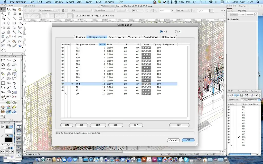
Can I ask you a favor? Could you attach a screenshot of your desktop? I'm curious about how you have the screen palettes:-)
 
confirmation: "gluing" is the fundamental command to "transfer" elements from one level to another
 
for the context I have created 1 unique layer that I use at full height.
the context generally keep it on the layer of the ground floor in a class called context.
In fact, in this last job I'm doing, I didn't even bother to give an (95)z to the layers... I was in a hurry but above all the plans are repeated identical;-)
Can I ask you a favor? Could you attach a screenshot of your desktop? I'm curious about how you spread the palettes on the screen
There he is. I don't think my palette order is very different from yours.
Here I am on mbp 15" so a little restricted, at work I have a 21" monitor, but the layout is the same.
Hi.
I do.
 

Attachments

  • Enterprise_Desktop.webp
    Enterprise_Desktop.webp
    203.3 KB · Views: 9
Listen, I realized that all the model is recalculated, if I take the ground floor that would then be nothing but your solid obtained from the extruded megacircle... He's high. a little upstairs and a little under plan 0. I tried to put myself in perspective and dissect everything so as to make an equal of all solids... But it doesn't make me do the cutter as in the plant... How can I solve this problem? If I could use cutter as in the plant would be fine... everything and away...
 
Well... I didn't understand anything.... it's impossible that the walls are not perpendicular to the work plan... or isn't that what you mean? !
 
Sorry.

My model is a model derived from the recalculating of another model.

I practically have solids that are beneath what should be the line of the soil. Do you know the sharp effect on solids when you do it on top\plant? here: I have to get the same effect on the same solids, but I have to cut them by setting the cutter while a visualization is on the prospectus.
 
I get it.
the seziona solid cutter in any view. at least here on vw2010.
now I try on 2009... and, yes, I confirm that even here it dissects in any view
I do.
 
I get it.
the seziona solid cutter in any view. at least here on vw2010.
now I try on 2009... and, yes, I confirm that even here it dissects in any view
I do.
Then the problem is me.

because if I put myself on the front view when I use the cutter key tells me that I can't do it

I return the message

"when the structured view of 3d glosses is activated, it is possible to use this tool only with the high \plant view or when the option "views 2d objects on the active polish" is activated.

What patience you have. I admire you
 
You may have enabled the display of aligned layers that I have no idea how it is called by you... here is stack layer, there will be "structured view", icon on the top right on the date bar. when active does not allow you to make changes. isolate the layer where you have to make the change and should work.
I do.
writing you the last message I realized myself that this would work. I expected confirmation. Thank you lory.b!
 
select the sectioned elements and the attribute shovel alter the thickness. or move them into a class created ad hoc (which would be better).
I do.
 
I'm starting the project! I wanted to know: but if I wanted to make a floor with a different pavement, which in the plant sees a particular retino and in 3d recognizes me a solid to insert the texture, how can I do?
 
You could create a symbol where in part 2d you check the retino and in part 3d you check the texture.
Part 3d could be a very small extruded polygon so it looks like a surface.
 
You could create a symbol where in part 2d you check the retino and in part 3d you check the texture.
Part 3d could be a very small extruded polygon so it looks like a surface.
Bye!

How do I independently assign the two aspects in different views?
 
create for example first part 2d, the cup(you serve for after), convert it into symbol with "create symbol", edit the symbol and vw will ask you if to act on the 2d or on the 3d, you choose 3d and with "paste in place" you will paste the 2d previously copied, then extrude it so that it becomes a solid.

Remember that the two parts(s 2d and solid 3d) are independent, if you change one you have to do it for the other.
 
as paolo.c suggests you have to create a hybrid symbol, with the two-dimensional object filled with the retino for viewing 2d and a 3d polylinea or an extrusion to which you assigned a texture, for viewing 3d.
I do.
 
Good morning!

I want to create a wall style that can edit me. In particular, I was interested in creating a kind of panels with intercapedins to be realized "arrorno" to a steel structure. How do you create your own wall style? Thank you!
 
Hi.
select the wall tool and in the options window you can add components. Once you have finished saving, on the top right of this window you will find the button, and you will see that in the list of styles you will also find your own.
I do.
 
I can't create a connection nurbs between the selected ones.

Could you "translate" the message he says? what are the connection radius and the normal? It is essential that it can create a fitting surface.


I wanted to create a loft with 2 tracks but 2 section curves!!!! Can't you do it?!?!? !
 

Forum statistics

Threads
44,997
Messages
339,767
Members
4
Latest member
ibt

Members online

No members online now.
Back
Top