You are using an out of date browser. It may not display this or other websites correctly.
You should upgrade or use an alternative browser.
You should upgrade or use an alternative browser.


meccanicamg
Guest
We could also put beautiful alettatures on the whole case, so as to increase thermal dissipation naturally passive. It would be necessary to do some small things otherwise it would be risky to do a very heavy work in economic terms so as not to get enough practical feedback as a heat reduction. It is also true that it is a student reducer, so even though well maintained and supervised by us professionals, we have that the application is entirely theoretical.I didn't read all the posts... only the first 2 pages and part of the last.
the vertical division thus is very particular but feasible, it is necessary to foresee a proper spindle of the case for assembly,
I would put in specially designed lubrication plant with sprayers contact points, about 3 knm to 1200 rpm are a high power, which generates a lot of heat, hardly dissipable with lubrication to beat if the operation is h24.
attention to the limit laps of the bearings!! by experience I always had difficulty!!! Also because I usually use 300 mm up and 1200rpm bearings heat a lot, therefore forced lubrication of bearings.
Is the intersection like input?? for a report 1 : 1.33 seems excessive (by evaluating the proportions of the images posted...) I have not seen quotas...
In the end, I tell you that everything you read here is true, but every reducer has a story to itself...
on the other hand it would be necessary to see also the accounts that made our friend ste8 on the trees, static and fatigue verification, as it has verified/dimensioned the dentate wheels especially module and width wheels (static + pitting + fatigue bending all according to one 8862 or according to ansi/agma norms). as it did the calculation of duration of the bearings, since bearings were mounted without shields therefore not "2z" or "rs". we do not know if the tits are cast iron or aluminum but we have hypothesized cast iron, so it dissipates little and keeps the heat very much. will the interfering shaft/wheel mount be guaranteed at regimen? what will happen when the reducer arrives at regime and it will be all hot 100/200/300 degrees? have you taken into account the thermal expansion of the trees at regime? and the loss of mechanical characteristics?
If you want there is an immensity to be evaluated and you must already have in mind all these things while you plan, but obviously ste8 is at first arms and we have reasoned all together and with time and experience will learn to analyze everything independently.
we see the drawings.. .
sampom
Guest
in fact seen now and "measured" eye on the monitor looks more like a 1.45 (approximately).Is the intersection like input?? for a report 1 : 1.33 seems to me excessive (by evaluating the proportions of the images posted. . )
ste8, what wheels did you use?
greetings
Mar
ste8
Guest
I never stop learning. . .are lubricated because turning the lower dentate wheels will produce abundant splashes of oil that will allow the lubrication of the upper organs.
thanks for the delucidazione!
meccanicamg
Guest
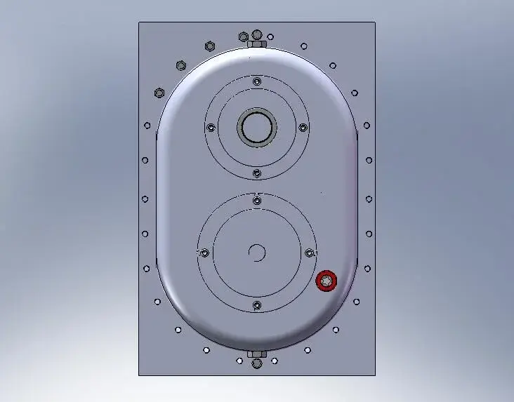
Why should it be a rectangular bad thing? the outer flange costs a patrimony and it does not serve anything. Can't you make a beautiful ring of a few centimeters holding the oval shape? then those screws are an infinite series and in the plug zone is too close.I'll give you some views of the reducer. I also inserted the screws as from your advice, are they too many?
but the ribs that I had marked you to do, did you only make four? and the rest of the semicasses? then the connection rays of the 4 cups compared to the plan where they are?
and caps for oil loading and unloading?
Attachments


ste8
Guest
Come on, I've done some of the things over here. :biggrin:We could also put beautiful alettatures on the whole case, so as to increase thermal dissipation naturally passive. It would be necessary to do some small things otherwise it would be risky to do a very heavy work in economic terms so as not to get enough practical feedback as a heat reduction. It is also true that it is a student reducer, so even though well maintained and supervised by us professionals, we have that the application is entirely theoretical.
on the other hand it would be necessary to see also the accounts that made our friend ste8 on the trees, static and fatigue verification, as it has verified/dimensioned the dentate wheels especially module and width wheels (static + pitting + fatigue bending all according to one 8862 or according to ansi/agma norms). as it did the calculation of duration of the bearings, since bearings were mounted without shields therefore not "2z" or "rs". we do not know if the tits are cast iron or aluminum but we have hypothesized cast iron, so it dissipates little and keeps the heat very much. will the interfering shaft/wheel mount be guaranteed at regimen? what will happen when the reducer arrives at regime and it will be all hot 100/200/300 degrees? have you taken into account the thermal expansion of the trees at regime? and the loss of mechanical characteristics?
If you want there is an immensity to be evaluated and you must already have in mind all these things while you plan, but obviously ste8 is at first arms and we have reasoned all together and with time and experience will learn to analyze everything independently.
we see the drawings.. .
1) shaft sized for static stresses, then fatigued and with the effects of carving.
2) Bearings tested for a duration of 15000 hours according to iso 281:1990/amd 2:2000 of skf.
3) dentate wheels first dimensional according to the forces to be transmitted and then with symmetrical correction of the toothing, verifying the teeth with bending and pitting according to standard uni 8862.
4) guaranteed interference by studying forced mast coupling (only on tree 2, which was what we should have checked).
5) as regards the operating temperature, 70/80°c were considered at the suggestion of the professor.
meccanicamg
Guest
: less evil. But now it fixes a little the bodywork of this reducer that ... no offense is brown and above all it is wasted a lot of material uselessly. then we wondered about z1 and z2 how much they are? then the number of screws... I would say that it is better 12 in everything and not 24. so they are too dense.Come on, I've done some of the things over here. :biggrin:
1) shaft sized for static stresses, then fatigued and with the effects of carving.
2) Bearings tested for a duration of 15000 hours according to iso 281:1990/amd 2:2000 of skf.
3) dentate wheels first dimensional according to the forces to be transmitted and then with symmetrical correction of the toothing, verifying the teeth with bending and pitting according to standard uni 8862.
4) guaranteed interference by studying forced mast coupling (only on tree 2, which was what we should have checked).
5) as regards the operating temperature, 70/80°c were considered at the suggestion of the professor.
ste8
Guest
:biggrin: ok boss! :biggrin:: less evil. But now it fixes a little the bodywork of this reducer that ... no offense is brown and above all it is wasted a lot of material uselessly. then we wondered about z1 and z2 how much they are? then the number of screws... I would say that it is better 12 in everything and not 24. so they are too dense.
I'm fixing the carcass, and then I have to ask you a question about the ribs. Get ready!
apart from the jokes, talk, exchange views with people like all of you, experts in the field, but above all kind and helpful, I was really pleased! Thank you again! we feel in half an hour (hope!)
meccanicamg
Guest
We are also pleased to discuss and reason. sometimes in the office it is not possible, it causes unavailability to dialogue since not all people think that discussing is profitable.:biggrin: ok boss! :biggrin:
I'm fixing the carcass, and then I have to ask you a question about the ribs. Get ready!
apart from the jokes, talk, exchange views with people like all of you, experts in the field, but above all kind and helpful, I was really pleased! Thank you again! we feel in half an hour (hope!)
Put the case on, then ask me the question about the ribs. I will answer you after dinner:
ste8
Guest
I'll be back, after a few problems with solid that got me killed!Why should it be a rectangular bad thing? the outer flange costs a patrimony and it does not serve anything. Can't you make a beautiful ring of a few centimeters holding the oval shape? then those screws are an infinite series and in the plug zone is too close.
but the ribs that I had marked you to do, did you only make four? and the rest of the semicasses? then the connection rays of the 4 cups compared to the plan where they are?
and caps for oil loading and unloading?
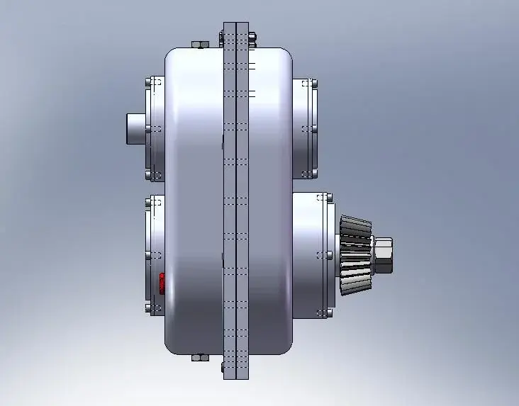
I still have to insert the commercial plugs, now I will, but in the meantime I place an image of the axieme and an internal view of a carcass, because I do not understand where you would recommend to put other ribs, since I had thought a carcass that traces the circumference of the wheels. But maybe you'll recommend me a thin carcass laterally?
Honestly, I hope I'm good, tomorrow I'd like to show him to the professor, hoping that he won't tell me that it's all to change, otherwise I'll send him here to you!
Attachments


meccanicamg
Guest
ohh finally the reducer:biggrin: If you don't put the right caps, I won't talk to you anymore.I'll be back, after a few problems with solid that got me killed!
I still have to insert the commercial plugs, now I will, but in the meantime I place an image of the axieme and an internal view of a carcass, because I do not understand where you would recommend to put other ribs, since I had thought a carcass that traces the circumference of the wheels. But maybe you'll recommend me a thin carcass laterally?
Honestly, I hope I'm good, tomorrow I'd like to show him to the professor, hoping that he won't tell me that it's all to change, otherwise I'll send him here to you!
then I start from the fact that every semicarter is an oval with two domes (as from my hand sketch in pdf in the first post). the ribs all go around this oval because surely decreasing the thickness is necessary to strengthen.
If with the internal carcass, you retrace the circumferences of the toothed wheels, nothing more, and above all you don't need anything to use all that giant oval... and then all the gearbox should be revisited.
all the carcass must have that thickness on all sides!!! (I took it for granted)
If he tells you that it is all to change, you motivate all the choices and explain to him as a young technician your motivations. then if you don't understand anything and support your idea make it happy. You know how many times I said to my boss, "You're right, if it's okay with you and it's all right, and I don't give a damn, money is yours." you don't always have to deal with smart people. you always look for comparison, then each make his choices.
ah for the plugs, do a small pavement on the round surface and then do the hole, so the seal rests on a floor. then if you were to do what makes an attractive thing you can draw in transparency and in yellow the volume of oil inside the reducer.
ste8
Guest
Okok tappi changed!ohh finally the reducer:biggrin: If you don't put the right caps, I won't talk to you anymore.
then I start from the fact that every semicarter is an oval with two domes (as from my hand sketch in pdf in the first post). the ribs all go around this oval because surely decreasing the thickness is necessary to strengthen.
If with the internal carcass, you retrace the circumferences of the toothed wheels, nothing more, and above all you don't need anything to use all that giant oval... and then all the gearbox should be revisited.
all the carcass must have that thickness on all sides!!! (I took it for granted)
If he tells you that it is all to change, you motivate all the choices and explain to him as a young technician your motivations. then if you don't understand anything and support your idea make it happy. You know how many times I said to my boss, "You're right, if it's okay with you and it's all right, and I don't give a damn, money is yours." you don't always have to deal with smart people. you always look for comparison, then each make his choices.
ah for the plugs, do a small pavement on the round surface and then do the hole, so the seal rests on a floor. then if you were to do what makes an attractive thing you can draw in transparency and in yellow the volume of oil inside the reducer.
Now, I don't understand why the kind of cut I made inside the two semicarters would be good. there is a space of a few cm between the concavity in the bucket and the toothed wheel.
and more, I can't make a "in revolution" ribbing along the entire surface with solidworks.
meccanicamg
Guest
If you realize the ribs that form an 8 inside are not good and do not serve anything. You have to make them along the oval.Okok tappi changed!
Now, I don't understand why the kind of cut I made inside the two semicarters would be good. there is a space of a few cm between the concavity in the bucket and the toothed wheel.
and more, I can't make a "in revolution" ribbing along the entire surface with solidworks.
the procedure is as follows:
- create a rib in a vertical position (the blue one)
- create a sketch of path (which is the inner oval)
- curved repeat (active offsets and tangency and fair spacing)
Attachments

cacciatorino
Guest
Remember that in castings the thickness must be large homogeneous, to avoid blows and cracks, or at least tensions, due to the withdrawal.Okok tappi changed!
Now, I don't understand why the kind of cut I made inside the two semicarters would be good. there is a space of a few cm between the concavity in the bucket and the toothed wheel.
and more, I can't make a "in revolution" ribbing along the entire surface with solidworks.
Hi.
ste8
Guest

ste8
Guest
z1=36, z2=48, where z1 is the number of teeth of the wheel above and z2 the one below. the module is 6 mm.in fact seen now and "measured" eye on the monitor looks more like a 1.45 (approximately).
ste8, what wheels did you use?
greetings
Mar
meccanicamg
Guest
Good!after hours and hours of fighting with solid works, I really hope I'm done!
tomorrow I show to the prof and if you give me the ok mold everything and delivery for the exam!
I keep you updated!
Hello and thank you all!
steak
keep us updated... You can enjoy the well-deserved rest.
ste8
Guest
Get me back! I list below the corrections that the prof suggested to me:
- What are you doing? He didn't seem necessary to do it, but he didn't break much.
- exhaust gorges where the bearings are drawn and where there are the two cylindrical wheels, and vabbé...
- change the position of the oil indicator, because the reducer is positioned horizontally and not vertically as I drew it.
- "extend" the conical wheel, used the hub of the same instead of the shouldering obtained on the tree (and here comes a problem with solid that I explain to you later!).
- on the tree 1 at the top, I was "recommended to reverse shouldering and space, because so would be too complex disassembly!
That's all!
Back to my problem, I can't change the wheels created with the toolbox. I will explain my procedure:
- I create new together;
- insert the wheel I need with the characteristics I need;
I can lighten it, but I can't create a hub extrusion!
- at this point I save it as part, I draw what I need, but I remain all the edges and when I do the section I only dissect the extrusions and not the wheel.
I put some pictures!
Thank you.
I'm sorry.
Attachments


meccanicamg
Guest
I don't know. something had to say otherwise you feel a useless man... like almost everyone.Get me back! I list below the corrections that the prof suggested to me:
- What are you doing? He didn't seem necessary to do it, but he didn't break much.
- exhaust gorges where the bearings are drawn and where there are the two cylindrical wheels, and vabbé...
- change the position of the oil indicator, because the reducer is positioned horizontally and not vertically as I drew it.
- "extend" the conical wheel, used the hub of the same instead of the shouldering obtained on the tree (and here comes a problem with solid that I explain to you later!).
- on the tree 1 at the top, I was "recommended to reverse shouldering and space, because so would be too complex disassembly!
That's all!
Back to my problem, I can't change the wheels created with the toolbox. I will explain my procedure:
- I create new together;
- insert the wheel I need with the characteristics I need;
I can lighten it, but I can't create a hub extrusion!
- at this point I save it as part, I draw what I need, but I remain all the edges and when I do the section I only dissect the extrusions and not the wheel.
I put some pictures!
Thank you.
I'm sorry.
I don't know what you're doing with the toolboxes. or do everything with the toolbox and then save the separate part and you can do other jobs, otherwise it does not work. use the command merge result when you do extrusions.
Don't let it go! it works quietly... it has to work. if you ever put the problems more clearly than we see.
- Exhaust gorges need us
- the ribs tell him you learned a new command and serve because it's too thin the case
- turn the tree shoulders 1
- I didn't understand that.
ste8
Guest
to calculate the coupling shaft hub, I had considered a coupling length equal to the band width. the professor told me to consider as width of the coupling a value about 1.5*diameter of calettamento. Now, however, I do not want to go to change everything for such a thing and I have considered a coupling width of 90 mm (diameter of 70 mm). apart from this detail I have already discussed with him, I can't bring this stretch back on the solid design!I don't know. something had to say otherwise you feel a useless man... like almost everyone.
I don't know what you're doing with the toolboxes. or do everything with the toolbox and then save the separate part and you can do other jobs, otherwise it does not work. use the command merge result when you do extrusions.
Don't let it go! it works quietly... it has to work. if you ever put the problems more clearly than we see.
- Exhaust gorges need us
- the ribs tell him you learned a new command and serve because it's too thin the case
- turn the tree shoulders 1
- I didn't understand that.
is worth the same speech (only the part of the drawing) for the conical wheel.
place two designs to try to make you understand! with the arrows I'm going to tell my problem! all the parts indicated with the arrows are parts of the wheels and not of the tree (do not mind the error on the section of the cylindrical wheel, because there is the wrong diameter).
I hope I've explained
Hi.

